 |
Motore di ricerca datesheet componenti elettronici |
|
|
Motore di ricerca datesheet componenti elettronici |
|
The question interval is too short.
Please try again in a few seconds.

Hello, Please ask a question about MIC2174C-1YMM Datasheet
# Example questions:
➢ What is the purpose of the short circuit protection feature as demonstrated in the functional characteristics section?
➢ What is the typical current limit threshold at 0v feedback voltage?
➢ How does increasing temperature affect the switching frequency?
| Part No. | MIC2174C-1YMM |
| Manufacturer | MICREL |
| Size | 706 Kbytes |
| Pages | 27 pages |
| Description | Synchronous Buck Controller Featuring Adaptive On-Time Control 40V Input, 300kHz |



1. General Information & Purpose
️· Device: MIC2174/MIC2174C. This is a synchronous buck switching regulator (DC-DC converter).
️· Purpose: Designed for high-efficiency voltage regulation in a wide range of applications, including portable devices, power management, and battery charging.
️· Key Features: Synchronous rectification (using an external MOSFET), high efficiency, adjustable switching frequency, current limit, short-circuit protection, and thermal shutdown.
2. Electrical Characteristics (Highlights – there are many detailed specifications in the document)
️· Input Voltage Range: Not explicitly stated but implied to be suitable for common battery voltages.
️· Output Voltage: Adjustable (through external components).
️· Switching Frequency: Adjustable (through external components, allowing optimization for size or efficiency).
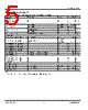
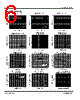
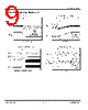
️· Current Limit: The current limit is specified as varying with the feedback voltage percentage, see page 3 for graph.
️· Quiescent Supply Current: Page 3 shows the quiescent supply current vs. input voltage, showing low current draw.
3. Protection Features
️· Current Limit: Protects against overcurrent conditions.
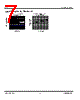
️· Short-Circuit Protection: The datasheet includes a graph (functional diagram) showing the response to a short circuit condition – demonstrating how the regulator handles it.
️· Thermal Shutdown: Provides overtemperature protection.
4. Functional Diagram & Block Diagram
️· Figure 3 (Short Circuit): Visual representation of the regulator's behavior during a short circuit, showing input and output voltage/current waveforms.
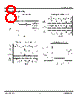
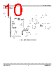
️· Figure 1 (Block Diagram): Illustrates the major functional blocks of the regulator, including the PWM controller, gate driver, error amplifier, and protection circuitry.
5. Key Graphs & Charts (Illustrative)
️· Current Limit vs. Feedback Voltage Percentage: Shows how the current limit changes with different feedback voltage settings.
️· Quiescent Supply Current vs. Input Voltage: Illustrates the power consumption of the regulator at different input voltages.
️· Switching Frequency vs. HSD Voltage/Temperature: Showcases how the switching frequency changes in response to various conditions.
️· Feedback Voltage vs. Temperature: Demonstrates the stability of the output voltage against variations in temperature.
6. Functional Characteristics
️· Short-Circuit Recovery: The functional characteristics sections are not described, but they would likely detail the regulator’s behavior under various operating conditions (startup, transient response, etc.).
Overall Summary
The MIC2174/MIC2174C datasheet provides comprehensive details about a synchronous buck switching regulator. It is designed for high efficiency and flexibility, allowing designers to tailor the performance to specific application requirements. The datasheet includes a lot of graphical information, so these are critical to understand the device’s performance parameters.
1. General Information & Purpose
️· Device: MIC2174/MIC2174C. This is a synchronous buck switching regulator (DC-DC converter).
️· Purpose: Designed for high-efficiency voltage regulation in a wide range of applications, including portable devices, power management, and battery charging.
️· Key Features: Synchronous rectification (using an external MOSFET), high efficiency, adjustable switching frequency, current limit, short-circuit protection, and thermal shutdown.
2. Electrical Characteristics (Highlights – there are many detailed specifications in the document)
️· Input Voltage Range: Not explicitly stated but implied to be suitable for common battery voltages.
️· Output Voltage: Adjustable (through external components).
️· Switching Frequency: Adjustable (through external components, allowing optimization for size or efficiency).
️· Current Limit: The current limit is specified as varying with the feedback voltage percentage, see page 3 for graph.
️· Quiescent Supply Current: Page 3 shows the quiescent supply current vs. input voltage, showing low current draw.
3. Protection Features
️· Current Limit: Protects against overcurrent conditions.
️· Short-Circuit Protection: The datasheet includes a graph (functional diagram) showing the response to a short circuit condition – demonstrating how the regulator handles it.
️· Thermal Shutdown: Provides overtemperature protection.
4. Functional Diagram & Block Diagram
️· Figure 3 (Short Circuit): Visual representation of the regulator's behavior during a short circuit, showing input and output voltage/current waveforms.
️· Figure 1 (Block Diagram): Illustrates the major functional blocks of the regulator, including the PWM controller, gate driver, error amplifier, and protection circuitry.
5. Key Graphs & Charts (Illustrative)
️· Current Limit vs. Feedback Voltage Percentage: Shows how the current limit changes with different feedback voltage settings.
️· Quiescent Supply Current vs. Input Voltage: Illustrates the power consumption of the regulator at different input voltages.
️· Switching Frequency vs. HSD Voltage/Temperature: Showcases how the switching frequency changes in response to various conditions.
️· Feedback Voltage vs. Temperature: Demonstrates the stability of the output voltage against variations in temperature.
6. Functional Characteristics
️· Short-Circuit Recovery: The functional characteristics sections are not described, but they would likely detail the regulator’s behavior under various operating conditions (startup, transient response, etc.).
Overall Summary
The MIC2174/MIC2174C datasheet provides comprehensive details about a synchronous buck switching regulator. It is designed for high efficiency and flexibility, allowing designers to tailor the performance to specific application requirements. The datasheet includes a lot of graphical information, so these are critical to understand the device’s performance parameters.
| Part No. | MIC2174C-1YMM |
| Manufacturer | MICREL |
| Size | 706 Kbytes |
| Pages | 27 pages |
| Description | Synchronous Buck Controller Featuring Adaptive On-Time Control 40V Input, 300kHz |
| Lei ha avuto il aiuto da alldatasheet? [ DONATE ] |
Di alldatasheet | Richest di pubblicita | contatti | Privacy Policy | Collegamento alla scheda tecnica | scambio Link | Ricerca produttore All Rights Reserved©Alldatasheet.com |
| Russian : Alldatasheetru.com | Korean : Alldatasheet.co.kr | Spanish : Alldatasheet.es | French : Alldatasheet.fr | Italian : Alldatasheetit.com Portuguese : Alldatasheetpt.com | Polish : Alldatasheet.pl | Vietnamese : Alldatasheet.vn Indian : Alldatasheet.in | Mexican : Alldatasheet.com.mx | British : Alldatasheet.co.uk | New Zealand : Alldatasheet.co.nz |
|
Family Site : ic2ic.com |
icmetro.com |
 Italian ▼
  English
 Chinese
 German
 Japanese
 Russian
 Korean
 Spanish
 French
 Portuguese
 Polish
 Vietnamese
 Indian
 Mexican
 British
 New Zealand