 |
Motore di ricerca datesheet componenti elettronici |
|
|
Motore di ricerca datesheet componenti elettronici |
|
The question interval is too short.
Please try again in a few seconds.

Hello, Please ask a question about ATS685LSHTN-T Datasheet
# Example questions:
➢ What is the initial current state of the ats685 upon power-on?
➢ The document mentions both v sense(highside) and v sense(lowside). explain the difference between these two configurations and how they relate to the i_cc signal.
➢ How does the 'continuous update' algorithm adapt to variations in the magnetic field, and what parameters does it consider?
| Part No. | ATS685LSHTN-T |
| Manufacturer | ALLEGRO |
| Size | 445 Kbytes |
| Pages | 15 pages |
| Description | Two-Wire, Zero Speed Differential Gear Tooth Sensor IC |

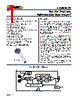
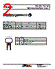
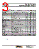
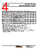
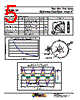
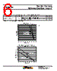
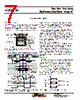
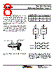
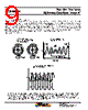

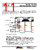




Okay, here's a summary of the provided text, breaking it down into key areas and concepts:
1. Device Overview: ATS685LSH Gear Tooth Sensor
️· Function: A two-wire, zero-speed gear tooth sensor IC. It detects gear rotation and provides a digital output signal (current amplitude).
️· Two-Wire Sensing: Requires an external sense resistor (R SENSE) to convert the current output to a voltage signal for measurement. Can be placed on either the VCC or GND pins, affecting the output signal's polarity.
️· Power-On Behavior: The device initially powers on in a high current state (I CC(High)).
️· Initial Edge Detection: Self-calibrates using the first detected teeth, requiring a brief "calibration" period (CAL I) for optimal performance.
2. Output Signal & Polarity
️· Output Polarity States: The polarity of the output voltage (V SENSE) depends on the location of the sense resistor (R SENSE) relative to VCC and GND.
- Low-Side Sensing (GND pin side): V SENSE is in phase with I CC.
- High-Side Sensing (VCC pin side): V SENSE is inverted relative to I CC.
️· Automatic Gain Control (AGC): The device uses the first three rising edges (high peaks) after power-on to calibrate the AGC, which optimizes the sensitivity to gear tooth signals.
3. Key Features and Algorithms
️· Continuous Update Algorithm: This algorithm adapts to changes in the magnetic field induced by the target. This helps compensate for issues like:
- Eccentric mounting (target not perfectly centered)
- Out-of-round target shape
- Target position shifts
️· AGC Calibration: The duration of the AGC calibration period (CAL I) can vary depending on the target feature opposite the sensor IC upon power-on, and the target speed.
4. Operational Sequence (simplified)
1. Power-On: Device starts in high current state.
2. Initial Edge Detection: The device detects the first teeth and begins a calibration period.
3. AGC Calibration: The device uses the first few rising edges to calibrate the AGC.
4. Running Mode: The device operates in normal gear tooth sensing mode.
Essentially, the ATS685LSH is a robust sensor designed to work reliably even under less-than-ideal conditions (eccentric mounting, etc.) through its adaptive algorithms and automatic calibration.
1. Device Overview: ATS685LSH Gear Tooth Sensor
️· Function: A two-wire, zero-speed gear tooth sensor IC. It detects gear rotation and provides a digital output signal (current amplitude).
️· Two-Wire Sensing: Requires an external sense resistor (R SENSE) to convert the current output to a voltage signal for measurement. Can be placed on either the VCC or GND pins, affecting the output signal's polarity.
️· Power-On Behavior: The device initially powers on in a high current state (I CC(High)).
️· Initial Edge Detection: Self-calibrates using the first detected teeth, requiring a brief "calibration" period (CAL I) for optimal performance.
2. Output Signal & Polarity
️· Output Polarity States: The polarity of the output voltage (V SENSE) depends on the location of the sense resistor (R SENSE) relative to VCC and GND.
- Low-Side Sensing (GND pin side): V SENSE is in phase with I CC.
- High-Side Sensing (VCC pin side): V SENSE is inverted relative to I CC.
️· Automatic Gain Control (AGC): The device uses the first three rising edges (high peaks) after power-on to calibrate the AGC, which optimizes the sensitivity to gear tooth signals.
3. Key Features and Algorithms
️· Continuous Update Algorithm: This algorithm adapts to changes in the magnetic field induced by the target. This helps compensate for issues like:
- Eccentric mounting (target not perfectly centered)
- Out-of-round target shape
- Target position shifts
️· AGC Calibration: The duration of the AGC calibration period (CAL I) can vary depending on the target feature opposite the sensor IC upon power-on, and the target speed.
4. Operational Sequence (simplified)
1. Power-On: Device starts in high current state.
2. Initial Edge Detection: The device detects the first teeth and begins a calibration period.
3. AGC Calibration: The device uses the first few rising edges to calibrate the AGC.
4. Running Mode: The device operates in normal gear tooth sensing mode.
Essentially, the ATS685LSH is a robust sensor designed to work reliably even under less-than-ideal conditions (eccentric mounting, etc.) through its adaptive algorithms and automatic calibration.
| Part No. | ATS685LSHTN-T |
| Manufacturer | ALLEGRO |
| Size | 445 Kbytes |
| Pages | 15 pages |
| Description | Two-Wire, Zero Speed Differential Gear Tooth Sensor IC |
| Lei ha avuto il aiuto da alldatasheet? [ DONATE ] |
Di alldatasheet | Richest di pubblicita | contatti | Privacy Policy | Collegamento alla scheda tecnica | scambio Link | Ricerca produttore All Rights Reserved©Alldatasheet.com |
| Russian : Alldatasheetru.com | Korean : Alldatasheet.co.kr | Spanish : Alldatasheet.es | French : Alldatasheet.fr | Italian : Alldatasheetit.com Portuguese : Alldatasheetpt.com | Polish : Alldatasheet.pl | Vietnamese : Alldatasheet.vn Indian : Alldatasheet.in | Mexican : Alldatasheet.com.mx | British : Alldatasheet.co.uk | New Zealand : Alldatasheet.co.nz |
|
Family Site : ic2ic.com |
icmetro.com |
 Italian ▼
  English
 Chinese
 German
 Japanese
 Russian
 Korean
 Spanish
 French
 Portuguese
 Polish
 Vietnamese
 Indian
 Mexican
 British
 New Zealand