 |
Motore di ricerca datesheet componenti elettronici |
|
|
Motore di ricerca datesheet componenti elettronici |
|
The question interval is too short.
Please try again in a few seconds.

Hello, Please ask a question about SL74HC393D Datasheet
# Example questions:
➢ What is the maximum clock frequency (at 6.0v) for the sl74hc393, as specified in the ac electrical characteristics section?
➢ What is the purpose of the 'cpd' parameter, and how is it used in calculating power consumption for the sl74hc393?
➢ What is the minimum pulse width required for the clock signal at 4.5v?
| Part No. | SL74HC393D |
| Manufacturer | SLS |
| Size | 50 Kbytes |
| Pages | 7 pages |
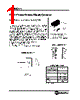
| Description | Dual 4-Stage Binary Ripple Counter |


## Summary of the SL74HC393 Datasheet Information
This document is a comprehensive datasheet for the SL74HC393, a 4-bit binary counter. Here's a breakdown of the key information:
1. Functionality:
️· The SL74HC393 is a synchronous, 4-bit binary counter. It increments on the positive (rising) edge of the clock pulse.
️· It can be used for a variety of counting applications.
️· It features asynchronous reset for immediate clearing of the counter.
2. Key Electrical Characteristics:
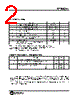
️· Supply Voltage (Vcc): Typically operates from 2.0V to 6.0V.
️· Maximum Clock Frequency (fmax): Up to 32 MHz (depending on Vcc).
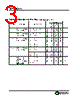
️· Propagation Delay (tPLH/tPHL): Time it takes for a signal to propagate through the counter. (Ranges from 9ns to 290ns depending on output and supply voltage).
️· Input Capacitance (CIN): 10 pF
️· Power Dissipation Capacitance (CPD): 40pF (typical)
️· Power Supply Current (ICC): Up to 80 µA (per package)
3. Timing Parameters:
️· Minimum Pulse Width (Tw): Defines the minimum duration of the clock and reset pulses for reliable operation (Ranges from 80ns to 190ns depending on pulse type and supply voltage)
️· Minimum Recovery Time (Trec): Defines the minimum time between the reset deactivation and the clock pulse. (50ns-75ns)
️· Input Rise/Fall Time (tr/tf): Maximum acceptable rise and fall times of input signals (Up to 1000ns)
4. Logic Diagram & Count Sequence:
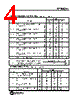
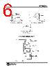
️· The datasheet provides an expanded logic diagram for understanding the internal connections of the counter.
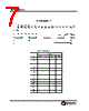
️· A count sequence table details the Q1-Q4 outputs for each count from 0 to 15.
5. Important Considerations:
️· Synchronous Operation: The counter's outputs change only on the rising edge of the clock signal, ensuring predictable operation.
️· Asynchronous Reset: Offers quick clearing without waiting for the clock.
️· Power Supply Compatibility: Designed for a wide range of supply voltages, making it versatile for different applications.
In essence, this datasheet provides all the necessary information for engineers and designers to properly integrate the SL74HC393 into their electronic circuits. It covers electrical characteristics, timing requirements, and logical functionality to ensure reliable performance and proper operation.
## Summary of the SL74HC393 Datasheet Information
This document is a comprehensive datasheet for the SL74HC393, a 4-bit binary counter. Here's a breakdown of the key information:
1. Functionality:
️· The SL74HC393 is a synchronous, 4-bit binary counter. It increments on the positive (rising) edge of the clock pulse.
️· It can be used for a variety of counting applications.
️· It features asynchronous reset for immediate clearing of the counter.
2. Key Electrical Characteristics:
️· Supply Voltage (Vcc): Typically operates from 2.0V to 6.0V.
️· Maximum Clock Frequency (fmax): Up to 32 MHz (depending on Vcc).
️· Propagation Delay (tPLH/tPHL): Time it takes for a signal to propagate through the counter. (Ranges from 9ns to 290ns depending on output and supply voltage).
️· Input Capacitance (CIN): 10 pF
️· Power Dissipation Capacitance (CPD): 40pF (typical)
️· Power Supply Current (ICC): Up to 80 µA (per package)
3. Timing Parameters:
️· Minimum Pulse Width (Tw): Defines the minimum duration of the clock and reset pulses for reliable operation (Ranges from 80ns to 190ns depending on pulse type and supply voltage)
️· Minimum Recovery Time (Trec): Defines the minimum time between the reset deactivation and the clock pulse. (50ns-75ns)
️· Input Rise/Fall Time (tr/tf): Maximum acceptable rise and fall times of input signals (Up to 1000ns)
4. Logic Diagram & Count Sequence:
️· The datasheet provides an expanded logic diagram for understanding the internal connections of the counter.
️· A count sequence table details the Q1-Q4 outputs for each count from 0 to 15.
5. Important Considerations:
️· Synchronous Operation: The counter's outputs change only on the rising edge of the clock signal, ensuring predictable operation.
️· Asynchronous Reset: Offers quick clearing without waiting for the clock.
️· Power Supply Compatibility: Designed for a wide range of supply voltages, making it versatile for different applications.
In essence, this datasheet provides all the necessary information for engineers and designers to properly integrate the SL74HC393 into their electronic circuits. It covers electrical characteristics, timing requirements, and logical functionality to ensure reliable performance and proper operation.
| Part No. | SL74HC393D |
| Manufacturer | SLS |
| Size | 50 Kbytes |
| Pages | 7 pages |
| Description | Dual 4-Stage Binary Ripple Counter |
| Lei ha avuto il aiuto da alldatasheet? [ DONATE ] |
Di alldatasheet | Richest di pubblicita | contatti | Privacy Policy | Collegamento alla scheda tecnica | scambio Link | Ricerca produttore All Rights Reserved©Alldatasheet.com |
| Russian : Alldatasheetru.com | Korean : Alldatasheet.co.kr | Spanish : Alldatasheet.es | French : Alldatasheet.fr | Italian : Alldatasheetit.com Portuguese : Alldatasheetpt.com | Polish : Alldatasheet.pl | Vietnamese : Alldatasheet.vn Indian : Alldatasheet.in | Mexican : Alldatasheet.com.mx | British : Alldatasheet.co.uk | New Zealand : Alldatasheet.co.nz |
|
Family Site : ic2ic.com |
icmetro.com |
 Italian ▼
  English
 Chinese
 German
 Japanese
 Russian
 Korean
 Spanish
 French
 Portuguese
 Polish
 Vietnamese
 Indian
 Mexican
 British
 New Zealand