 |
Motore di ricerca datesheet componenti elettronici |
|
|
Motore di ricerca datesheet componenti elettronici |
|
The question interval is too short.
Please try again in a few seconds.

Hello, Please ask a question about AS5134 Datasheet
# Example questions:
➢ Referring to table 6, what information is contained within bits d15-d9 of the 21-bit read data in 2- or 3-wire read-only mode?
➢ What is the significance of the 'tto' timing parameter as described in the detailed description section and what unit of measure is used?
➢ What are the key differences between the 3-wire read/write connection and the 3-wire read-only connection for the as5134?
| Part No. | AS5134 |
| Manufacturer | AMSCO |
| Size | 2Mb |
| Pages | 33 pages |
| Description | 360 Step Programmable High Speed Magnetic Rotary Encoder |









1. Device Overview:
️· Device: AS5134 Magnetic Encoder
️· Function: Provides angle information from a rotating magnet.
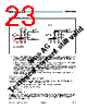
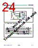
2. Connection Modes & Communication:
The AS5134 supports various communication methods, offering flexibility in integration:
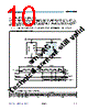
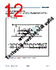
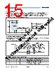
️· Serial 3-Wire R/W: Read/Write functionality, allowing commands and data exchange. Requires Chip Select (CS), Clock (DCLK), and Data In/Out (DIO) signals.
️· Serial 3-Wire Read-Only: Used when only angle data is needed, and no commands are sent. Requires CS, DCLK, and DIO. A pull-down resistor is needed.
️· Serial 2-Wire (R/W Mode): A reduced pin count option for read/write functionality. Uses CS, DCLK, and a shared DIO line.
️· Serial 2-Wire Differential SSI: A differential signal option.
️· 1-Wire PWM: Output angle information as a Pulse Width Modulated (PWM) signal.
️· Analog Output: Output angle as an analog voltage.
️· Quadrature A/B/Index: Provides incremental angle information.
️· Brushless DC Motor Commutation Mode: Supports commutation control for BLDC motors.
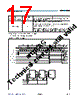
️· Daisy Chain Mode: Allows connecting multiple AS5134 devices in series.
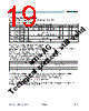
3. Key Parameters and Timing (from Tables):
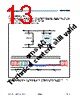
Serial 3-Wire R/W
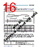
️· t0: Rising DCLK to CS: 15 ns
️· t1: Chip select to positive edge of DCLK: 15 ns
️· t3: Setup time command bit: 30 ns
️· t4: Hold time command bit: 30 ns
️· t5: Float time: 30 ns to DCLK/2
️· t6: Bus driving time: DCLK/2 + 0 to DCLK/2 + 30 ns
️· t7: Setup time data bit: DCLK/2 + 0 to DCLK/2 + 30 ns
️· t8: Hold time data bit: DCLK/2 + 0 to DCLK/2 + 30 ns
️· t9: Hold time chip select: 30 ns
️· t10: Bus floating time: 0 to 30 ns
️· tTO: Timeout period in 2-wire mode (from rising edge of DCLK): 17 to 27 µs (microseconds)
Serial 3-Wire Read-Only
️· Uses the same timing parameters as the Read/Write mode, but specific values aren't emphasized in this excerpt.
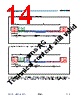
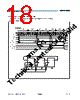
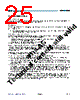
2-or 3-wire Read-only Serial Bit Sequence
️· C4, C3, C2, C1, C0 are command bits. '00000' selects the Read_Angle command.
️· lock, AGC (Automatic Gain Control), and Angle bits follow.
4. Important Notes:
️· C2 Input: Configures the device between 3-wire R/W (C2 = low) and 2-wire mode (C2 = high).
️· Read-Only Mode: Requires pull-down resistor on the DIO signal during initial command reception (first 5 bits).
️· Timing: All timing parameters (t0, t1, t3, etc.) are critical for reliable communication.
1. Device Overview:
️· Device: AS5134 Magnetic Encoder
️· Function: Provides angle information from a rotating magnet.
2. Connection Modes & Communication:
The AS5134 supports various communication methods, offering flexibility in integration:
️· Serial 3-Wire R/W: Read/Write functionality, allowing commands and data exchange. Requires Chip Select (CS), Clock (DCLK), and Data In/Out (DIO) signals.
️· Serial 3-Wire Read-Only: Used when only angle data is needed, and no commands are sent. Requires CS, DCLK, and DIO. A pull-down resistor is needed.
️· Serial 2-Wire (R/W Mode): A reduced pin count option for read/write functionality. Uses CS, DCLK, and a shared DIO line.
️· Serial 2-Wire Differential SSI: A differential signal option.
️· 1-Wire PWM: Output angle information as a Pulse Width Modulated (PWM) signal.
️· Analog Output: Output angle as an analog voltage.
️· Quadrature A/B/Index: Provides incremental angle information.
️· Brushless DC Motor Commutation Mode: Supports commutation control for BLDC motors.
️· Daisy Chain Mode: Allows connecting multiple AS5134 devices in series.
3. Key Parameters and Timing (from Tables):
Serial 3-Wire R/W
️· t0: Rising DCLK to CS: 15 ns
️· t1: Chip select to positive edge of DCLK: 15 ns
️· t3: Setup time command bit: 30 ns
️· t4: Hold time command bit: 30 ns
️· t5: Float time: 30 ns to DCLK/2
️· t6: Bus driving time: DCLK/2 + 0 to DCLK/2 + 30 ns
️· t7: Setup time data bit: DCLK/2 + 0 to DCLK/2 + 30 ns
️· t8: Hold time data bit: DCLK/2 + 0 to DCLK/2 + 30 ns
️· t9: Hold time chip select: 30 ns
️· t10: Bus floating time: 0 to 30 ns
️· tTO: Timeout period in 2-wire mode (from rising edge of DCLK): 17 to 27 µs (microseconds)
Serial 3-Wire Read-Only
️· Uses the same timing parameters as the Read/Write mode, but specific values aren't emphasized in this excerpt.
2-or 3-wire Read-only Serial Bit Sequence
️· C4, C3, C2, C1, C0 are command bits. '00000' selects the Read_Angle command.
️· lock, AGC (Automatic Gain Control), and Angle bits follow.
4. Important Notes:
️· C2 Input: Configures the device between 3-wire R/W (C2 = low) and 2-wire mode (C2 = high).
️· Read-Only Mode: Requires pull-down resistor on the DIO signal during initial command reception (first 5 bits).
️· Timing: All timing parameters (t0, t1, t3, etc.) are critical for reliable communication.
| Part No. | AS5134 |
| Manufacturer | AMSCO |
| Size | 2Mb |
| Pages | 33 pages |
| Description | 360 Step Programmable High Speed Magnetic Rotary Encoder |
| Lei ha avuto il aiuto da alldatasheet? [ DONATE ] |
Di alldatasheet | Richest di pubblicita | contatti | Privacy Policy | Collegamento alla scheda tecnica | scambio Link | Ricerca produttore All Rights Reserved©Alldatasheet.com |
| Russian : Alldatasheetru.com | Korean : Alldatasheet.co.kr | Spanish : Alldatasheet.es | French : Alldatasheet.fr | Italian : Alldatasheetit.com Portuguese : Alldatasheetpt.com | Polish : Alldatasheet.pl | Vietnamese : Alldatasheet.vn Indian : Alldatasheet.in | Mexican : Alldatasheet.com.mx | British : Alldatasheet.co.uk | New Zealand : Alldatasheet.co.nz |
|
Family Site : ic2ic.com |
icmetro.com |
 Italian ▼
  English
 Chinese
 German
 Japanese
 Russian
 Korean
 Spanish
 French
 Portuguese
 Polish
 Vietnamese
 Indian
 Mexican
 British
 New Zealand