 |
Motore di ricerca datesheet componenti elettronici |
|
|
Motore di ricerca datesheet componenti elettronici |
|
The question interval is too short.
Please try again in a few seconds.

Hello, Please ask a question about FR154-B Datasheet
# Example questions:
➢ What is the purpose of the test circuit shown?
➢ What is the typical peak reverse voltage (vrrm) for the fr156 diode?
➢ What is the typical forward voltage drop (vf) at 1a for these diodes as indicated in figure 3?
| Part No. | FR154-B |
| Manufacturer | RECTRON |
| Size | 35 Kbytes |
| Pages | 3 pages |
| Description | FAST RECOVERY RECTIFIER |

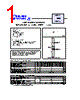
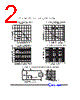


This document is a datasheet for a family of rectifier diodes manufactured by Rectron. Here's a breakdown of the information:
1. Device Overview:
️· Type: These are fast recovery rectifier diodes.
️· Series: FR151 to FR156 and their variants (like FR15x-T, -B, -P)
️· Purpose: Used for rectification in power supplies and other circuits requiring high-speed switching.
2. Key Specifications (gathered from tables and figures):
️· Voltage Rating: The datasheet implies a range, but doesn't explicitly state the maximum. The figures showing reverse voltage characteristics will give you that information.
️· Current Rating: Not explicitly stated, but implied by the graphs.
️· Forward Voltage Drop: Figure 3 ("Typical Instantaneous Forward Characteristics") shows the forward voltage vs. forward current.
️· Reverse Recovery Time: Figure 5 ("Test Circuit Diagram and Reverse Recovery Time Characteristic") illustrates the diode's reverse recovery time. This is crucial for high-frequency applications.
️· Temperature Range: Graphs show performance at different temperatures, indicating operating temperature limitations.
3. Figures & Graphs:
️· Figure 1: Typical Instantaneous Forward Characteristics: Plots forward voltage vs. forward current at different junction temperatures.
️· Figure 2: Typical Junction Capacitance: Shows how the junction capacitance changes with reverse voltage. Important for high-frequency performance.
️· Figure 3: Test Circuit Diagram and Reverse Recovery Time Characteristic: Illustrates the test setup and the waveform for measuring the reverse recovery time.
️· Figures 4 & 5: Show how various parameters change with temperature.
️· Figure 6: Presents reverse recovery time characteristics.
4. Variants:
️· `-T` suffix: Likely indicates a specific packaging or lead form.
️· `-B` suffix: Also likely a packaging or lead form variant.
️· `-P` suffix: Another packaging/lead form variant.
5. Mouser Link:
️· The datasheet includes links to Mouser Electronics for pricing, inventory, and ordering.
To get precise specifications you'd need to examine the actual datasheet diagrams and tables carefully.
1. Device Overview:
️· Type: These are fast recovery rectifier diodes.
️· Series: FR151 to FR156 and their variants (like FR15x-T, -B, -P)
️· Purpose: Used for rectification in power supplies and other circuits requiring high-speed switching.
2. Key Specifications (gathered from tables and figures):
️· Voltage Rating: The datasheet implies a range, but doesn't explicitly state the maximum. The figures showing reverse voltage characteristics will give you that information.
️· Current Rating: Not explicitly stated, but implied by the graphs.
️· Forward Voltage Drop: Figure 3 ("Typical Instantaneous Forward Characteristics") shows the forward voltage vs. forward current.
️· Reverse Recovery Time: Figure 5 ("Test Circuit Diagram and Reverse Recovery Time Characteristic") illustrates the diode's reverse recovery time. This is crucial for high-frequency applications.
️· Temperature Range: Graphs show performance at different temperatures, indicating operating temperature limitations.
3. Figures & Graphs:
️· Figure 1: Typical Instantaneous Forward Characteristics: Plots forward voltage vs. forward current at different junction temperatures.
️· Figure 2: Typical Junction Capacitance: Shows how the junction capacitance changes with reverse voltage. Important for high-frequency performance.
️· Figure 3: Test Circuit Diagram and Reverse Recovery Time Characteristic: Illustrates the test setup and the waveform for measuring the reverse recovery time.
️· Figures 4 & 5: Show how various parameters change with temperature.
️· Figure 6: Presents reverse recovery time characteristics.
4. Variants:
️· `-T` suffix: Likely indicates a specific packaging or lead form.
️· `-B` suffix: Also likely a packaging or lead form variant.
️· `-P` suffix: Another packaging/lead form variant.
5. Mouser Link:
️· The datasheet includes links to Mouser Electronics for pricing, inventory, and ordering.
| Part No. | FR154-B |
| Manufacturer | RECTRON |
| Size | 35 Kbytes |
| Pages | 3 pages |
| Description | FAST RECOVERY RECTIFIER |
| Lei ha avuto il aiuto da alldatasheet? [ DONATE ] |
Di alldatasheet | Richest di pubblicita | contatti | Privacy Policy | Collegamento alla scheda tecnica | scambio Link | Ricerca produttore All Rights Reserved©Alldatasheet.com |
| Russian : Alldatasheetru.com | Korean : Alldatasheet.co.kr | Spanish : Alldatasheet.es | French : Alldatasheet.fr | Italian : Alldatasheetit.com Portuguese : Alldatasheetpt.com | Polish : Alldatasheet.pl | Vietnamese : Alldatasheet.vn Indian : Alldatasheet.in | Mexican : Alldatasheet.com.mx | British : Alldatasheet.co.uk | New Zealand : Alldatasheet.co.nz |
|
Family Site : ic2ic.com |
icmetro.com |
 Italian ▼
  English
 Chinese
 German
 Japanese
 Russian
 Korean
 Spanish
 French
 Portuguese
 Polish
 Vietnamese
 Indian
 Mexican
 British
 New Zealand