 |
Motore di ricerca datesheet componenti elettronici |
|
|
Motore di ricerca datesheet componenti elettronici |
|
The question interval is too short.
Please try again in a few seconds.

Hello, Please ask a question about ATS685 Datasheet
# Example questions:
➢ What determines the polarity of the output signal and how can it be configured?
➢ What is the initial current state of the ats685 upon power-on?
➢ Describe how the 'continuous update' algorithm functions and what it adapts to in the target's magnetic field.
| Part No. | ATS685 |
| Manufacturer | ALLEGRO |
| Size | 443 Kbytes |
| Pages | 15 pages |
| Description | Two-Wire, Zero Speed Differential Gear Tooth Sensor IC |






1. Overview & Function
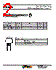
️· Device Type: Differential Gear Tooth Sensor IC (ATS685LSH).
️· Primary Function: Detects and interprets signals from rotating gears, providing a digital output signal (current amplitude).
️· Two-Wire Operation: Operates using two wires (VCC and GND), simplifying connections.
️· Direction of Rotation: The device reads the signal when the target rotates from pin 1 to pin 4 (left to right when looking at the IC).
️· Polarity: The output signal polarity is configurable (High-Side or Low-Side sensing) affecting the voltage relative to the current flow.
2. Key Features & Operating Principles
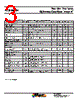
️· Continuous Update of Switchpoints: Adaptable to variations in target position and gear shape (eccentric mounts, out-of-round gears). This is achieved through a continuous monitoring and adjustment of the switching thresholds.
️· Power-On Behavior: Starts in a high current state (I CC(High)) upon power application.
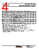
️· Initial Edge Detection/Calibration: Self-calibrates during the initial rotation, leading to a brief period of reduced accuracy (CAL I). The first three rising edges are used for Automatic Gain Control (AGC) calibration.
️· Adaptability: The device is able to adapt to changes within a gear's magnetic field.
3. Power-On & Calibration
️· Power-On State: Initially powers on in the high current state (I CC(High)).
️· Calibration Period (CAL I): Occurs after power-on, leading to temporary reduced accuracy. Uses first three rising edges for Automatic Gain Control (AGC).
️· Factors Affecting Calibration: Speed of rotation during power-on and the initial target feature position affect the CAL I period.
4. Signal Configuration & Polarity
️· Sensing Sides: Configurable for High-Side or Low-Side sensing.
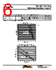
️· Output Voltage (V SENSE): Voltage is determined by placement of a sense resistor (R SENSE) on either the VCC or GND pin.
️· Polarity Relationship:
- High-Side: V SENSE(HighSide) is inverted relative to I CC.
- Low-Side: V SENSE(LowSide) is in phase with I CC.
5. Technical Considerations
️· Target Rotation Direction: Critical to proper operation (pin 1 to pin 4).
️· Initialization: Brief period (CAL I) after power-up where accuracy is reduced while the device calibrates.
️· Operating Frequency: Initial edge detection is affected by the operating frequency (f OP ≤ 200 Hz).
1. Overview & Function
️· Device Type: Differential Gear Tooth Sensor IC (ATS685LSH).
️· Primary Function: Detects and interprets signals from rotating gears, providing a digital output signal (current amplitude).
️· Two-Wire Operation: Operates using two wires (VCC and GND), simplifying connections.
️· Direction of Rotation: The device reads the signal when the target rotates from pin 1 to pin 4 (left to right when looking at the IC).
️· Polarity: The output signal polarity is configurable (High-Side or Low-Side sensing) affecting the voltage relative to the current flow.
2. Key Features & Operating Principles
️· Continuous Update of Switchpoints: Adaptable to variations in target position and gear shape (eccentric mounts, out-of-round gears). This is achieved through a continuous monitoring and adjustment of the switching thresholds.
️· Power-On Behavior: Starts in a high current state (I CC(High)) upon power application.
️· Initial Edge Detection/Calibration: Self-calibrates during the initial rotation, leading to a brief period of reduced accuracy (CAL I). The first three rising edges are used for Automatic Gain Control (AGC) calibration.
️· Adaptability: The device is able to adapt to changes within a gear's magnetic field.
3. Power-On & Calibration
️· Power-On State: Initially powers on in the high current state (I CC(High)).
️· Calibration Period (CAL I): Occurs after power-on, leading to temporary reduced accuracy. Uses first three rising edges for Automatic Gain Control (AGC).
️· Factors Affecting Calibration: Speed of rotation during power-on and the initial target feature position affect the CAL I period.
4. Signal Configuration & Polarity
️· Sensing Sides: Configurable for High-Side or Low-Side sensing.
️· Output Voltage (V SENSE): Voltage is determined by placement of a sense resistor (R SENSE) on either the VCC or GND pin.
️· Polarity Relationship:
- High-Side: V SENSE(HighSide) is inverted relative to I CC.
- Low-Side: V SENSE(LowSide) is in phase with I CC.
5. Technical Considerations
️· Target Rotation Direction: Critical to proper operation (pin 1 to pin 4).
️· Initialization: Brief period (CAL I) after power-up where accuracy is reduced while the device calibrates.
️· Operating Frequency: Initial edge detection is affected by the operating frequency (f OP ≤ 200 Hz).
| Part No. | ATS685 |
| Manufacturer | ALLEGRO |
| Size | 443 Kbytes |
| Pages | 15 pages |
| Description | Two-Wire, Zero Speed Differential Gear Tooth Sensor IC |
| Lei ha avuto il aiuto da alldatasheet? [ DONATE ] |
Di alldatasheet | Richest di pubblicita | contatti | Privacy Policy | Collegamento alla scheda tecnica | scambio Link | Ricerca produttore All Rights Reserved©Alldatasheet.com |
| Russian : Alldatasheetru.com | Korean : Alldatasheet.co.kr | Spanish : Alldatasheet.es | French : Alldatasheet.fr | Italian : Alldatasheetit.com Portuguese : Alldatasheetpt.com | Polish : Alldatasheet.pl | Vietnamese : Alldatasheet.vn Indian : Alldatasheet.in | Mexican : Alldatasheet.com.mx | British : Alldatasheet.co.uk | New Zealand : Alldatasheet.co.nz |
|
Family Site : ic2ic.com |
icmetro.com |
 Italian ▼
  English
 Chinese
 German
 Japanese
 Russian
 Korean
 Spanish
 French
 Portuguese
 Polish
 Vietnamese
 Indian
 Mexican
 British
 New Zealand