 |
Motore di ricerca datesheet componenti elettronici |
|
|
Motore di ricerca datesheet componenti elettronici |
|
The question interval is too short.
Please try again in a few seconds.

Hello, Please ask a question about MIC2290BML Datasheet
# Example questions:
➢ How is the output voltage of the mic2290 adjusted, and what formula is provided to calculate the output voltage based on feedback resistor values?
➢ What is the recommended inductor value for most applications and what is a trade-off associated with using a larger inductance value?
➢ Explain how it functions and why it's important for the mlf™ package option.
| Part No. | MIC2290BML |
| Manufacturer | MICREL |
| Size | 98 Kbytes |
| Pages | 12 pages |
| Description | 2mm 횞 2mm PWM Boost Regulator with Internal Schotty Diode |






1. Overview & Function
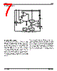
️· What it is: The MIC2290 is a constant frequency, PWM (Pulse Width Modulation) current-mode boost regulator. Boost regulators increase a DC input voltage to a higher DC output voltage.
️· How it works:
- Uses a 1.2MHz oscillator.
- Includes slope compensation.
- Uses a current amplifier to measure switch current.
- Compares feedback voltage (from output) with an internal 1.24V reference (via feedback resistors).
- PWM generator controls the output transistor, switching it on and off to regulate the output voltage.
️· Block Diagram: (Refer to Figure 1 in the document - not reproduced here). It shows VIN, FB (Feedback), EN (Enable), OUT, and key internal blocks.
2. Functional Description Details
️· PWM Control: The regulator uses a constant frequency PWM technique. The output transistor is switched on and off based on comparisons between the current loop signal and the voltage loop signal.
️· Feedback: The output voltage is regulated through feedback resistors (R1 and R2) that determine the voltage applied to the feedback pin. The desired output voltage can be calculated using a formula (see below).
3. Applications & Component Selection
️· Typical Application Circuit: (Refer to Figure 2) Shows a boost circuit with an inductor (L1), input capacitor, output capacitor, and the MIC2290.
️· Duty Cycle:
- The duty cycle (on/off time ratio) is a critical parameter. A maximum duty cycle of 85% is recommended to ensure proper operation.
️· Inductor Selection:
- Recommended inductance: 10µH (a good balance between cost, size, performance).
- Larger inductors reduce ripple current and improve efficiency, but may require increased output capacitance to maintain stability.
- Right Half Plane Zero (RHPZ) frequency calculation is provided to determine capacitor requirements.
️· Output Capacitor Selection:
- X5R or X7R ceramic capacitors are recommended.
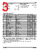
- Capacitance values vary based on the desired output voltage. Refer to Table 1 for guidelines.
️· Input Capacitor: Minimum 1µF ceramic capacitor recommended.
️· Feedback Resistors: Used to set the output voltage. The output voltage is determined by R1 and R2, using this equation:
```
V_OUT = 1.24V * (R1 / R2) + 1.24V
```
Where V_OUT is the desired output voltage.
4. Protection & Other Features
️· Overvoltage Protection (OVP): The MLF™ package option includes an overvoltage protection function. If the feedback pin is shorted to ground, the switch will shut off to prevent damage.
️· Right Half Plane Zero: A consideration for component selection.
5. Specific Numerical Values from the Text
️· Oscillator Frequency: 1.2 MHz
️· Reference Voltage (VREF): 1.24V
️· Maximum Duty Cycle: 85%
️· Recommended Inductance (L1): 10µH
️· Minimum Input Capacitor: 1µF
1. Overview & Function
️· What it is: The MIC2290 is a constant frequency, PWM (Pulse Width Modulation) current-mode boost regulator. Boost regulators increase a DC input voltage to a higher DC output voltage.
️· How it works:
- Uses a 1.2MHz oscillator.
- Includes slope compensation.
- Uses a current amplifier to measure switch current.
- Compares feedback voltage (from output) with an internal 1.24V reference (via feedback resistors).
- PWM generator controls the output transistor, switching it on and off to regulate the output voltage.
️· Block Diagram: (Refer to Figure 1 in the document - not reproduced here). It shows VIN, FB (Feedback), EN (Enable), OUT, and key internal blocks.
2. Functional Description Details
️· PWM Control: The regulator uses a constant frequency PWM technique. The output transistor is switched on and off based on comparisons between the current loop signal and the voltage loop signal.
️· Feedback: The output voltage is regulated through feedback resistors (R1 and R2) that determine the voltage applied to the feedback pin. The desired output voltage can be calculated using a formula (see below).
3. Applications & Component Selection
️· Typical Application Circuit: (Refer to Figure 2) Shows a boost circuit with an inductor (L1), input capacitor, output capacitor, and the MIC2290.
️· Duty Cycle:
- The duty cycle (on/off time ratio) is a critical parameter. A maximum duty cycle of 85% is recommended to ensure proper operation.
️· Inductor Selection:
- Recommended inductance: 10µH (a good balance between cost, size, performance).
- Larger inductors reduce ripple current and improve efficiency, but may require increased output capacitance to maintain stability.
- Right Half Plane Zero (RHPZ) frequency calculation is provided to determine capacitor requirements.
️· Output Capacitor Selection:
- X5R or X7R ceramic capacitors are recommended.
- Capacitance values vary based on the desired output voltage. Refer to Table 1 for guidelines.
️· Input Capacitor: Minimum 1µF ceramic capacitor recommended.
️· Feedback Resistors: Used to set the output voltage. The output voltage is determined by R1 and R2, using this equation:
```
V_OUT = 1.24V * (R1 / R2) + 1.24V
```
Where V_OUT is the desired output voltage.
4. Protection & Other Features
️· Overvoltage Protection (OVP): The MLF™ package option includes an overvoltage protection function. If the feedback pin is shorted to ground, the switch will shut off to prevent damage.
️· Right Half Plane Zero: A consideration for component selection.
5. Specific Numerical Values from the Text
️· Oscillator Frequency: 1.2 MHz
️· Reference Voltage (VREF): 1.24V
️· Maximum Duty Cycle: 85%
️· Recommended Inductance (L1): 10µH
️· Minimum Input Capacitor: 1µF
| Part No. | MIC2290BML |
| Manufacturer | MICREL |
| Size | 98 Kbytes |
| Pages | 12 pages |
| Description | 2mm 횞 2mm PWM Boost Regulator with Internal Schotty Diode |
| Lei ha avuto il aiuto da alldatasheet? [ DONATE ] |
Di alldatasheet | Richest di pubblicita | contatti | Privacy Policy | Collegamento alla scheda tecnica | scambio Link | Ricerca produttore All Rights Reserved©Alldatasheet.com |
| Russian : Alldatasheetru.com | Korean : Alldatasheet.co.kr | Spanish : Alldatasheet.es | French : Alldatasheet.fr | Italian : Alldatasheetit.com Portuguese : Alldatasheetpt.com | Polish : Alldatasheet.pl | Vietnamese : Alldatasheet.vn Indian : Alldatasheet.in | Mexican : Alldatasheet.com.mx | British : Alldatasheet.co.uk | New Zealand : Alldatasheet.co.nz |
|
Family Site : ic2ic.com |
icmetro.com |
 Italian ▼
  English
 Chinese
 German
 Japanese
 Russian
 Korean
 Spanish
 French
 Portuguese
 Polish
 Vietnamese
 Indian
 Mexican
 British
 New Zealand