|
Motore di ricerca datesheet componenti elettronici |
|
|
Motore di ricerca datesheet componenti elettronici |
|
HMC974LC3CTR-R5 Scheda tecnica(PDF) 10 Page - Analog Devices |
|
|
|||||||||||||||||||||||||||||
HMC974LC3CTR-R5 Scheda tecnica(HTML) 10 Page - Analog Devices |
|
|
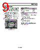
10 / 12 page  HMC974LC3C Data Sheet Rev. E | Page 10 of 12 APPLICATIONS INFORMATION EVALUATION BOARD The HMC974LC3C evaluation printed circuit board (PCB) must use RF circuit design techniques. Signal lines must have 50 Ω impedance while the package ground leads must connect directly to the ground plane of the PCB. The exposed metal package base must connect to VEE. Ensure the top and bottom ground planes connect together with via holes. The evaluation PCB shown in Figure 13 is available from Analog Devices, Inc., upon request. Figure 14 shows the EVAL-HMC974LC3C schematic. Figure 15 shows the typical application circuit. Table 5. Bill of Materials Reference Designator Description J1 Eight-position vertical header J2 to J7 K connector, SRI J8 Terminal strip, single row, 3-pin JP1, JP2 Two position vertical header C1 to C3, C5, C6, C8 to C10, C15 100 pF capacitor, 0402 C4, C7, C11 330 pF capacitor, 0402 C12 to C14 4.7 μF tantalum capacitor TP1 to TP4 DC pin U1 HMC974LC3C window comparator PCB EVAL-HMC974LC3C evaluation board, circuit board material is either Rogers 4350 or Arlon 25FR Figure 13. Evaluation Printed Circuit Board |
|
|
Link URL |
| Lei ha avuto il aiuto da alldatasheet? [ DONATE ] |
Di alldatasheet | Richest di pubblicita | contatti | Privacy Policy | Collegamento alla scheda tecnica | scambio Link | Ricerca produttore All Rights Reserved©Alldatasheet.com |
| Russian : Alldatasheetru.com | Korean : Alldatasheet.co.kr | Spanish : Alldatasheet.es | French : Alldatasheet.fr | Italian : Alldatasheetit.com Portuguese : Alldatasheetpt.com | Polish : Alldatasheet.pl | Vietnamese : Alldatasheet.vn Indian : Alldatasheet.in | Mexican : Alldatasheet.com.mx | British : Alldatasheet.co.uk | New Zealand : Alldatasheet.co.nz |
|
Family Site : ic2ic.com |
icmetro.com |
 Italian ▼
 English
 Chinese
 German
 Japanese
 Russian
 Korean
 Spanish
 French
 Italian
 Portuguese
 Polish
 Vietnamese
 Indian
 Mexican
 British
 New Zealand