|
Motore di ricerca datesheet componenti elettronici |
|
|
Motore di ricerca datesheet componenti elettronici |
|
ATS643LSH-I2 Scheda tecnica(PDF) 11 Page - Allegro MicroSystems |
|
|
|||||||||||||||||||||||||||||
ATS643LSH-I2 Scheda tecnica(HTML) 11 Page - Allegro MicroSystems |
|
|
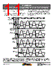
11 / 16 page  11 ATS643-DS, Rev. 1 Worcester, Massachusetts 01615-0036 (508) 853-5000 115 Northeast Cutoff, Box 15036 www.allegromicro.com Allegro MicroSystems, Inc. Self-Calibrating, Zero-Speed Differential GTS with Continuous Update ATS643LSH Power-On State Operation. The ATS643 is guaranteed to power-on in the high current state, ICC(High). Initial Edge Detection. The device self-calibrates using the initial teeth sensed, and then enters Running mode. This results in reduced accuracy for a brief period (less than four teeth), however, it allows the device to optimize for continuous update yielding adaptive sensing during Running mode. As shown in figure 5, the first three high peak signals are used to calibrate AGC. However, there is a slight variance in the duration of ini- tialization, depending on what target feature is nearest the sensor when power-on occurs. Figure 5. Power-on initial edge detection. This figure demonstrates four typical power-on scenarios. All of these examples assume that the target is moving relative to the sensor in the direction indicated. The length of time required to overcome Start Mode Hysteresis, as well as the combined effect of whether it is overcome in a positive or negative direction plus whether the next edge is in that same or opposite polarity, affect the point in time when AGC calibration begins. Three high peaks are always required for AGC calibration. Target (Gear) Output VPROC VPROC VPROC VPROC Output Output Output Power-on over valley Power-on at rising edge Power-on over tooth Power-on at falling edge AGC Calibration Running Mode AGC Calibration Running Mode AGC Calibration Running Mode AGC Calibration Running Mode Sensor Position 1 3 4 2 1 2 4 3 Start Mode Hysteresis Overcome Start Mode Hysteresis Overcome Start Mode Hysteresis Overcome Start Mode Hysteresis Overcome |
|
|
Link URL |
| Lei ha avuto il aiuto da alldatasheet? [ DONATE ] |
Di alldatasheet | Richest di pubblicita | contatti | Privacy Policy | Collegamento alla scheda tecnica | scambio Link | Ricerca produttore All Rights Reserved©Alldatasheet.com |
| Russian : Alldatasheetru.com | Korean : Alldatasheet.co.kr | Spanish : Alldatasheet.es | French : Alldatasheet.fr | Italian : Alldatasheetit.com Portuguese : Alldatasheetpt.com | Polish : Alldatasheet.pl | Vietnamese : Alldatasheet.vn Indian : Alldatasheet.in | Mexican : Alldatasheet.com.mx | British : Alldatasheet.co.uk | New Zealand : Alldatasheet.co.nz |
|
Family Site : ic2ic.com |
icmetro.com |
 Italian ▼
 English
 Chinese
 German
 Japanese
 Russian
 Korean
 Spanish
 French
 Italian
 Portuguese
 Polish
 Vietnamese
 Indian
 Mexican
 British
 New Zealand