|
Motore di ricerca datesheet componenti elettronici |
|
|
Motore di ricerca datesheet componenti elettronici |
|
A1696PKHTN-RDBPTYCD Scheda tecnica(PDF) 8 Page - Allegro MicroSystems |
|
|
|||||||||||||||||||||||||||||
A1696PKHTN-RDBPTYCD Scheda tecnica(HTML) 8 Page - Allegro MicroSystems |
|
|
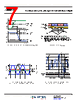
8 / 14 page  Position Sensor IC with Speed and Direction Output A1696PKH 8 Allegro MicroSystems 955 Perimeter Road Manchester, NH 03103-3353 U.S.A. www.allegromicro.com FUNCTIONAL DESCRIPTION Sensing Technology The sensor IC contains three Hall elements used in three differ- ential pairs to provide an electrical output signal containing infor- mation regarding target edge position and direction of rotation. Target Profiling After proper power is applied to the sensor IC, it is capable of providing digital information that is representative of the mechanical or magnetic features of a rotating target. The wave- form diagrams in Figure 7 present the automatic translation of the target profiles, from their induced magnetic profiles to the digital output signal of the sensor IC. Three differential mag- netic profiles are used to determine the location of the switching feature as well as the direction of rotation. While the location of the switching feature is determined from the differential magnetic profile (referred to as the speed channel), the direction of rotation is determined by the relative amplitude comparison of two low resolution normalized direction channels. Direction Detection The sensor IC compares the relative amplitude values of the two low resolution normalized direction signals at the speed channel switch point location to determine which direction the target is rotating. The direction of rotation is then communicated through the output pulse width. While in calibration mode, direction information is not available. As a result of this, forward output pulses (tW(FWD)) are always given in calibration, independent of the true target rotation direction. NOTE: For proper functionality, the output must be programmed such that the signature region is a non-switching feature (see Application Information section). The sensor IC can be programmed such that the output will provide forward pulses (tW(FWD)) when the target rotation is from pin 1 to pin 3 (Option F) or from pin 3 to pin 1 (Option R). This is illustrated in Figure 8, with the arrow on the target indicating direction of rotation. Figure 7: Magnetic Profile. The magnetic profile reflects the features of the target, allowing the sensor IC to present an accurate digital output. BST Device Orientation to Target Package Case Branded Face Target Magnetic Profile +B –B Mechanical Position (Target moves past device pin 1 to pin 3) N S S Target (Radial Ring Magnet) E1 E2 E3 N IC Internal Differential Analog Signals, VPROC Detected Channel Switching Device Output Direction Channel Direction Channel Speed Channel Speed Channel This pole sensed earlier This pole sensed later Speed Channel Element Pitch (Pin 1 Side) (Pin 3 Side) (Top View of Package Case) Speed Channel Element Pitch Figure 8: Rotation Direction Definitions Pin 1 Pin 3 N N N S N S S S Forward pulses (t ) generated for rotation from pin 1 to pin 3 W(FWD) Pin 1 Pin 3 Rotatin (Ring magnet or ferromagnetic) g Target Branded Face of KH Package Option F N N N S N S S S Rotatin (Ring magnet or ferromagnetic) g Target Option R Forward pulses (t W(FWD)) generated for rotation from pin 3 to pin 1 Branded Face of KH Package |
|
|
Link URL |
| Lei ha avuto il aiuto da alldatasheet? [ DONATE ] |
Di alldatasheet | Richest di pubblicita | contatti | Privacy Policy | Collegamento alla scheda tecnica | scambio Link | Ricerca produttore All Rights Reserved©Alldatasheet.com |
| Russian : Alldatasheetru.com | Korean : Alldatasheet.co.kr | Spanish : Alldatasheet.es | French : Alldatasheet.fr | Italian : Alldatasheetit.com Portuguese : Alldatasheetpt.com | Polish : Alldatasheet.pl | Vietnamese : Alldatasheet.vn Indian : Alldatasheet.in | Mexican : Alldatasheet.com.mx | British : Alldatasheet.co.uk | New Zealand : Alldatasheet.co.nz |
|
Family Site : ic2ic.com |
icmetro.com |
 Italian ▼
 English
 Chinese
 German
 Japanese
 Russian
 Korean
 Spanish
 French
 Italian
 Portuguese
 Polish
 Vietnamese
 Indian
 Mexican
 British
 New Zealand