|
Motore di ricerca datesheet componenti elettronici |
|
|
Motore di ricerca datesheet componenti elettronici |
|
ST1114E Scheda tecnica(PDF) 6 Page - Silicon Touch Technology Inc. |
|
|
|||||||||||||||||||||||||||||
ST1114E Scheda tecnica(HTML) 6 Page - Silicon Touch Technology Inc. |
|
|
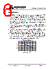
6 / 7 page  點晶科技股份有限公司 SILICON TOUCH TECHNOLOGY INC. ST1114E/ST1114K/ST1114P SP-ST1114EKP-A.011 Version :A.011 Page :5 Application Notes The FGR pin is an open-drained output with built-in pull-up resistor about 100K Ω and outputs the same frequency with HIN pin for ST1114E, the half frequency of HIN pin for ST1114K, and rotation detection result for ST1114P. An additional resistor can be used to pull up the FGR voltage to the appropriate level which depends on the voltage level of the monitoring/control system. For the ST1114P, the output of RD is at logical low state when fan is operating and logical high state when fan is lock. The resistor R1 connected between system power and VDD of HALL IC and driver increase system stability. The suggestion value of R1 is about 75Ω for 12V application. There is no requirement of the capacitor between VDD and GND in normal applications. The connection of this capacitance will increase stability of operation, special when the motor is operating at large current or low voltage. The power dissipated by the IC varies widely with the supply voltage, the output current, and loading. It is important to ensure the application does not exceed the allowable power dissipation of the IC package. The recommended motor driver power dissipation versus temperature is depicted as follows: Power Dissipation-Temperature 0 50 100 150 200 250 300 350 400 0 25 50 75 100 125 150 Ambient Temperature ( ℃ ) |
|
|
Link URL |
| Lei ha avuto il aiuto da alldatasheet? [ DONATE ] |
Di alldatasheet | Richest di pubblicita | contatti | Privacy Policy | Collegamento alla scheda tecnica | scambio Link | Ricerca produttore All Rights Reserved©Alldatasheet.com |
| Russian : Alldatasheetru.com | Korean : Alldatasheet.co.kr | Spanish : Alldatasheet.es | French : Alldatasheet.fr | Italian : Alldatasheetit.com Portuguese : Alldatasheetpt.com | Polish : Alldatasheet.pl | Vietnamese : Alldatasheet.vn Indian : Alldatasheet.in | Mexican : Alldatasheet.com.mx | British : Alldatasheet.co.uk | New Zealand : Alldatasheet.co.nz |
|
Family Site : ic2ic.com |
icmetro.com |
 Italian ▼
 English
 Chinese
 German
 Japanese
 Russian
 Korean
 Spanish
 French
 Italian
 Portuguese
 Polish
 Vietnamese
 Indian
 Mexican
 British
 New Zealand