|
Motore di ricerca datesheet componenti elettronici |
|
|
Motore di ricerca datesheet componenti elettronici |
|
MAPS-010163 Scheda tecnica(PDF) 6 Page - M/A-COM Technology Solutions, Inc. |
|
|
|||||||||||||||||||||||||||||
MAPS-010163 Scheda tecnica(HTML) 6 Page - M/A-COM Technology Solutions, Inc. |
|
|
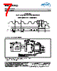
6 / 7 page  6 Digital Phase Shifter 6-Bit, 1.4 - 2.4 GHz Rev. V4 MAPS-010163 • North America Tel: 800.366.2266 • Europe Tel: +353.21.244.6400 • India Tel: +91.80.43537383 • China Tel: +86.21.2407.1588 Visit www.macomtech.com for additional data sheets and product information. M/A-COM Technology Solutions Inc. and its affiliates reserve the right to make changes to the product(s) or information contained herein without notice. ADVANCED: Data Sheets contain information regarding a product M/A-COM Technology Solutions is considering for development. Performance is based on target specifications, simulated results, and/or prototype measurements. Commitment to develop is not guaranteed. PRELIMINARY: Data Sheets contain information regarding a product M/A-COM Technology Solutions has under development. Performance is based on engineering tests. Specifications are typical. Mechanical outline has been fixed. Engineering samples and/or test data may be available. Commitment to produce in volume is not guaranteed. P/S LE Mode 1 X Serial 0 N/A Direct Parallel Serial Mode Direct Parallel Mode The serial control interface (SERIN, CLK, LE, SEROUT) is compatible with the SPI protocol. SPI mode is activated when P/S is kept high. The 6-bit serial word must be loaded with the MSB first. After shifting in the 6 bit word, a rising edge on LE will set the phase shifter to the desired state. While LE is high the CLK is masked to protect the data while implementing the change. SEROUT is SERIN delayed by 6 clock cycles. When P/S is low, the serial control interface is disabled. When P/S is set high, Pins 22, 23, and 24 have the LE, CLK, and SER IN function. In serial mode operation, the outputs will stay constant while LE is kept low. The parallel mode is enabled when P/S is set low. In the direct parallel mode, the phase shifter is controlled by the parallel control inputs directly. When P/S is set low, Pins 22, 23, and 24 have the D3, D2, and D1 function. Modes of Operation: Serial and Direct Parallel Mode Truth Table Serial Interface Timing Characteristics Symbol Parameter Typical Performance Units -40°C +25°C +85°C tSCK Min. Serial Clock Period 100 100 100 ns tCS Min. Control Set-up Time 20 20 20 ns tCH Min. Control Hold Time 20 20 20 ns tLS Min. LE Set-up Time 10 10 10 ns tLEW Min. LE Pulse Width 10 10 10 ns tLH Min. Serial Clock Hold Time from LE 10 10 10 ns tLES Min. LE Pulse Spacing 630 630 630 ns Truth Table (Digital Phase Shifter) 7 7. 0 = CMOS Low; 1 = CMOS High, X is CMOS Low or High D5 D4 D3 D2 D1 Phase Shift 0 0 0 0 0 Reference Phase 0 0 0 0 1 5.6 deg 0 0 0 1 0 11.2 deg 0 0 1 0 0 22.5 deg 0 1 0 0 0 45 deg 1 0 0 0 0 90 deg 1 1 1 1 1 354.4 deg D6 0 0 0 0 0 0 1 1 0 0 0 0 0 180 deg |
|
|
Link URL |
| Lei ha avuto il aiuto da alldatasheet? [ DONATE ] |
Di alldatasheet | Richest di pubblicita | contatti | Privacy Policy | Collegamento alla scheda tecnica | scambio Link | Ricerca produttore All Rights Reserved©Alldatasheet.com |
| Russian : Alldatasheetru.com | Korean : Alldatasheet.co.kr | Spanish : Alldatasheet.es | French : Alldatasheet.fr | Italian : Alldatasheetit.com Portuguese : Alldatasheetpt.com | Polish : Alldatasheet.pl | Vietnamese : Alldatasheet.vn Indian : Alldatasheet.in | Mexican : Alldatasheet.com.mx | British : Alldatasheet.co.uk | New Zealand : Alldatasheet.co.nz |
|
Family Site : ic2ic.com |
icmetro.com |
 Italian ▼
 English
 Chinese
 German
 Japanese
 Russian
 Korean
 Spanish
 French
 Italian
 Portuguese
 Polish
 Vietnamese
 Indian
 Mexican
 British
 New Zealand