|
Motore di ricerca datesheet componenti elettronici |
|
|
Motore di ricerca datesheet componenti elettronici |
|
AD7477SRT-R2 Scheda tecnica(PDF) 17 Page - Analog Devices |
|
|
|||||||||||||||||||||||||||||
AD7477SRT-R2 Scheda tecnica(HTML) 17 Page - Analog Devices |
|
|
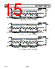
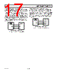
17 / 20 page  REV. D AD7476/AD7477/AD7478 –17– AD7476/AD7477/AD7478 to DSP56xxx Interface The connection diagram in Figure 20 shows how the AD7476/ AD7477/AD7478 can be connected to the SSI (Synchronous Serial Interface) of the DSP56xxx family of DSPs from Motorola. The SSI is operated in Synchronous Mode (SYN bit in CRB =1) with internally generated word frame sync for both Tx and Rx (Bits FSL1 = 0 and FSL0 = 0 in CRB). Set the word length to 16 by setting bits WL1 = 1 and WL0 = 0 in CRA. To implement the Power-Down mode on the AD7476/AD7477/ AD7478, the word length can be changed to eight bits by setting bits WL1 = 0 and WL0 = 0 in CRA. It should be noted that for signal processing applications, it is imperative that the frame synchronization signal from the DSP56xxx provides equidistant sampling. SDATA CS SRD SC2 AD7476/ AD7477/ AD7478* SCLK DSP56xxx* SCK *ADDITIONAL PINS OMITTED FOR CLARITY Figure 20. Interfacing to the DSP56xxx AD7476/AD7477/AD7478 to MC68HC16 Interface The Serial Peripheral Interface (SPI) on the MC68HC16 is configured for Master Mode (MSTR = 1), the Clock Polarity Bit (CPOL) = 1, and the Clock Phase Bit (CPHA) = 0. The SPI is configured by writing to the SPI Control Register (SPCR)—see the 68HC16 User Manual. The serial transfer will take place as a 16-bit operation when the SIZE bit in the SPCR register is set to SIZE = 1. To implement the Power-Down mode with an 8-bit transfer, set SIZE = 0. A connection diagram is shown in Figure 21. SDATA CS MISO/PMC0 SS/PMC3 AD7476/ AD7477/ AD7478* SCLK MC68HC16* SCLK/PMC2 *ADDITIONAL PINS OMITTED FOR CLARITY Figure 21. Interfacing to the MC68HC16 |
|
|
Link URL |
| Lei ha avuto il aiuto da alldatasheet? [ DONATE ] |
Di alldatasheet | Richest di pubblicita | contatti | Privacy Policy | Collegamento alla scheda tecnica | scambio Link | Ricerca produttore All Rights Reserved©Alldatasheet.com |
| Russian : Alldatasheetru.com | Korean : Alldatasheet.co.kr | Spanish : Alldatasheet.es | French : Alldatasheet.fr | Italian : Alldatasheetit.com Portuguese : Alldatasheetpt.com | Polish : Alldatasheet.pl | Vietnamese : Alldatasheet.vn Indian : Alldatasheet.in | Mexican : Alldatasheet.com.mx | British : Alldatasheet.co.uk | New Zealand : Alldatasheet.co.nz |
|
Family Site : ic2ic.com |
icmetro.com |
 Italian ▼
 English
 Chinese
 German
 Japanese
 Russian
 Korean
 Spanish
 French
 Italian
 Portuguese
 Polish
 Vietnamese
 Indian
 Mexican
 British
 New Zealand