|
Motore di ricerca datesheet componenti elettronici |
|
|
Motore di ricerca datesheet componenti elettronici |
|
AS5147 Scheda tecnica(PDF) 9 Page - ams AG |
|
|
|||||||||||||||||||||||||||||
AS5147 Scheda tecnica(HTML) 9 Page - ams AG |
|
|
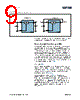
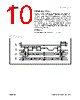
9 / 35 page  ams Datasheet: 2014-Jun-27 [v1-04] AS5147 – 9 Detaile d Desc rip t ion Figure 11: 5.0V and 3.3V Power Supply Options After applying power to the chip, the power-on time (tpon) must elapse before the AS5147 provides the first valid data. Dynamic Angle Error Compensation The AS5147 uses 4 integrated Hall sensors which produce a voltage proportional to the orthogonal component of the magnetic field to the die. These voltage signals are amplified, filtered, and converted into the digital domain to allow the CORDIC digital block to calculate the angle of the magnetic vector. Propagation of these signals through the analog front-end and digital back-end generates a fixed delay between the time of measurement and the availability of the measured angle at the outputs. This latency generates a dynamic angle error represented by the product of the angular speed ( ω)and the system propagation delay (tdelay): DAE = ω x tdelay The dynamic angle compensation block calculates the current magnet rotation speed ( ω) and multiplies it with the system propagation delay (tdelay) to determine the correction angle to reduce this error. At constant speed, the residual system propagation delay is tdelay_DAEC. The angle represented on the PWM interface is not compensated by the Dynamic Angle Error Compensation algorithm. it is also possible to disable the Dynamic Angle Error Compensation with the DAECDIS setting. Disabling the Dynamic Angle Error Compensation gives a noise benefit of 0.016 degree rms.This setting can be advantageous for low speed (under 100 RPM) respectively static positioning applications. 1µF 100nF 4.5 - 5.5V VDD3V3 GND VDD 5.0V Operation LDO AS5147 100nF 3.0 – 3.6V VDD3V3 GND VDD 3.3V Operation LDO AS5147 |
|
Link URL |
| Lei ha avuto il aiuto da alldatasheet? [ DONATE ] |
Di alldatasheet | Richest di pubblicita | contatti | Privacy Policy | Collegamento alla scheda tecnica | scambio Link | Ricerca produttore All Rights Reserved©Alldatasheet.com |
| Russian : Alldatasheetru.com | Korean : Alldatasheet.co.kr | Spanish : Alldatasheet.es | French : Alldatasheet.fr | Italian : Alldatasheetit.com Portuguese : Alldatasheetpt.com | Polish : Alldatasheet.pl | Vietnamese : Alldatasheet.vn Indian : Alldatasheet.in | Mexican : Alldatasheet.com.mx | British : Alldatasheet.co.uk | New Zealand : Alldatasheet.co.nz |
|
Family Site : ic2ic.com |
icmetro.com |
 Italian ▼
 English
 Chinese
 German
 Japanese
 Russian
 Korean
 Spanish
 French
 Italian
 Portuguese
 Polish
 Vietnamese
 Indian
 Mexican
 British
 New Zealand