|
Motore di ricerca datesheet componenti elettronici |
|
|
Motore di ricerca datesheet componenti elettronici |
|
IDT7M1003S40C Scheda tecnica(PDF) 7 Page - Integrated Device Technology |
|
|
|||||||||||||||||||||||||||||
IDT7M1003S40C Scheda tecnica(HTML) 7 Page - Integrated Device Technology |
|
|
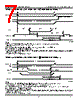
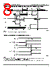
7 / 11 page  IDT7M1001/1003 128K/64K x 8 CMOS DUAL-PORT STATIC RAM MODULE MILITARY AND COMMERCIAL TEMPERATURE RANGES 7.5 7 TIMING WAVEFORM OF WRITE CYCLE NO. 1 (R/ W W CONTROLLED TIMING)(1,3,5,8) ADDRESS OE CS t WC t OHZ (9) t AW R/W t WP(2) t AS t WHZ(9) DATA OUT DATA IN (4) (4) t OW (9) t DW t DH t WR (7) DATA VALID (6) 2804 drw 08 TIMING WAVEFORM OF WRITE CYCLE NO. 2 ( CS CS CONTROLLED TIMING)(1,3,5,8) NOTES: 1. R/ W must be HIGH during all address transitions. 2. A write occurs during the overlap (tWP) of a LOW UB or LB and a LOW CS and a LOW R/W for memory array writing cycle. 3. tWR is measured from the earlier of CS or R/W (or SEM or R/W) going HIGH to the end of write cycle. 4. During this period, the I/O pins are in the output state and input signals must not be applied. 5. If the CS or SEM LOW transition occurs simultaneously with or after the R/W LOW transition, the outputs remain in the high-impedance state. 6. Timing depends on which enable signal is asserted last. 7. Timing depends on which enable signal is de-asserted first. 8. If OE is LOW during a R/W controlled write cycle, the write pulse width must be the larger of tWP or (tWZ + tDW) to allow the I/O drivers to turn off and data to be placed on the bus for the required tDW. If OE is HIGH during an R/W controlled write cycle, this requirement does not apply and the write pulse can be as short as the specified tWP. 9. This parameter is guaranteed by design but not tested. NOTES: 1. R/ W is HIGH for Read Cycles 2. Device is continuously enabled. CS = LOW. UB or LB = LOW. This waveform cannot be used for semaphore reads. 3. Addresses valid prior to or coincident with CS transition low. 4. OE = LOW. 5. To access RAM, CS = LOW, UB or LB = LOW, SEM = H. To access semaphore, CS = HIGH and SEM = LOW. 6. Timing depends on which enable signal is asserted last. 7. Timing depends on which enable signal is de-asserted first. 8. If OE is LOW during a R/W controlled write cycle, the write pulse width must be larger of tWP or (tWZ + tDW) to allow the I/O drivers to turn off and data to be placed on the bus for the required tDW. If OE is HIGH during a R/W controlled write cycle, this requirement does not apply and the write pulse width be as short as the specified tWP. 9. This parameter is guaranteed by design but not tested. ADDRESS t WC DATA IN t DW t DH DATA VALID t AW R/W t WP (2) t WR(7) CS t AS (6) UB LB or 2804 drw 09 |
|
|
Link URL |
| Lei ha avuto il aiuto da alldatasheet? [ DONATE ] |
Di alldatasheet | Richest di pubblicita | contatti | Privacy Policy | Collegamento alla scheda tecnica | scambio Link | Ricerca produttore All Rights Reserved©Alldatasheet.com |
| Russian : Alldatasheetru.com | Korean : Alldatasheet.co.kr | Spanish : Alldatasheet.es | French : Alldatasheet.fr | Italian : Alldatasheetit.com Portuguese : Alldatasheetpt.com | Polish : Alldatasheet.pl | Vietnamese : Alldatasheet.vn Indian : Alldatasheet.in | Mexican : Alldatasheet.com.mx | British : Alldatasheet.co.uk | New Zealand : Alldatasheet.co.nz |
|
Family Site : ic2ic.com |
icmetro.com |
 Italian ▼
 English
 Chinese
 German
 Japanese
 Russian
 Korean
 Spanish
 French
 Italian
 Portuguese
 Polish
 Vietnamese
 Indian
 Mexican
 British
 New Zealand