|
Motore di ricerca datesheet componenti elettronici |
|
|
Motore di ricerca datesheet componenti elettronici |
|
MQWI40C Scheda tecnica(PDF) 6 Page - Minmax Technology Co., Ltd. |
|
|
|||||||||||||||||||||||||||||
MQWI40C Scheda tecnica(HTML) 6 Page - Minmax Technology Co., Ltd. |
|
|
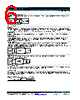
6 / 6 page  MQWI40C SERIES DC/DC Power Module 40W Minmax Technology Co., Ltd. 18, Sin Sin Road, An-Ping Industrial District, Tainan 702, Taiwan Tel: 886-6-2923150 Fax: 886-6-2923149 E-mail: sales@minmax.com.tw 2015/05/22 REV:2 Page 6 of 66 Test Setup Peak-to-Peak Output Noise Measurement Test Scope measurement should be made by using a BNC socket, measurement bandwidth is 0-20 MHz. Position the load between 50 mm and 75 mm from the DC/DC Converter. +Out -Out +Vin -Vin Single Output DC / DC Converter Resistive Load Scope Copper Strip Cout Copper Strip Technical Notes Remote On/Off Positive logic remote on/off turns the module on during a logic high voltage on the remote on/off pin, and off during a logic low. To turn the power module on and off, the user must supply a switch to control the voltage between the on/off terminal and the -Vin terminal. The switch can be an open collector or equivalent. A logic low is 0V to 1.2V. A logic high is 3.5V to 12V. The maximum sink current at the on/off terminal (Pin 1) during a logic low is -100μA. Overload Protection To provide hiccup mode protection in a fault (output overload) condition, the unit is equipped with internal current limiting circuitry and can endure overload for an unlimited duration. Overvoltage Protection The output overvoltage clamp consists of control circuitry, which is independent of the primary regulation loop, that monitors the voltage on the output terminals. The control loop of the clamp has a higher voltage set point than the primary loop. This provides a redundant voltage control that reduces the risk of output overvoltage. The OVP level can be found in the output data. Input Source Impedance The power module should be connected to a low ac-impedance input source. Highly inductive source impedances can affect the stability of the power module. In applications where power is supplied over long lines and output loading is high, it may be necessary to use a capacitor at the input to ensure startup. Capacitor mounted close to the power module helps ensure stability of the unit, it is recommended to use a good quality low Equivalent Series Resistance (ESR < 1.0 Ω at 100 KHz) capacitor of a 10μF for the 24V and 48V devices. + +Out -Out +Vin -Vin DC / DC Converter Load DC Power Source + - Cin Output Ripple Reduction A good quality low ESR capacitor placed as close as practicable across the load will give the best ripple and noise performance. To reduce output ripple, it is recommended to use 4.7μF capacitors at the output. +Out -Out +Vin -Vin Load DC Power Source + - Cout Single Output DC / DC Converter Maximum Capacitive Load The MQWI40C series has limitation of maximum connected capacitance at the output. The power module may be operated in current limiting mode during start-up, affecting the ramp-up and the startup time. The maximum capacitance can be found in the data sheet. Thermal Considerations Many conditions affect the thermal performance of the power module, such as orientation, airflow over the module and board spacing. To avoid exceeding the maximum temperature rating of the components inside the power module, the case temperature must be kept below 95℃. The derating curves are determined from measurements obtained in a test setup. DUT Position of air velocity probe and thermocouple 50mm / 2in Air Flow 15mm / 0.6in |
|
|
Link URL |
| Lei ha avuto il aiuto da alldatasheet? [ DONATE ] |
Di alldatasheet | Richest di pubblicita | contatti | Privacy Policy | Collegamento alla scheda tecnica | scambio Link | Ricerca produttore All Rights Reserved©Alldatasheet.com |
| Russian : Alldatasheetru.com | Korean : Alldatasheet.co.kr | Spanish : Alldatasheet.es | French : Alldatasheet.fr | Italian : Alldatasheetit.com Portuguese : Alldatasheetpt.com | Polish : Alldatasheet.pl | Vietnamese : Alldatasheet.vn Indian : Alldatasheet.in | Mexican : Alldatasheet.com.mx | British : Alldatasheet.co.uk | New Zealand : Alldatasheet.co.nz |
|
Family Site : ic2ic.com |
icmetro.com |
 Italian ▼
 English
 Chinese
 German
 Japanese
 Russian
 Korean
 Spanish
 French
 Italian
 Portuguese
 Polish
 Vietnamese
 Indian
 Mexican
 British
 New Zealand