|
Motore di ricerca datesheet componenti elettronici |
|
|
Motore di ricerca datesheet componenti elettronici |
|
SI9150 Scheda tecnica(PDF) 5 Page - Vishay Siliconix |
|
|
|||||||||||||||||||||||||||||
SI9150 Scheda tecnica(HTML) 5 Page - Vishay Siliconix |
|
|
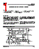
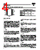
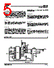
5 / 5 page  Si9150 Vishay Siliconix Document Number: 70020 S-40752—Rev. F, 19-Apr-04 www.vishay.com 5 Pin 9: CT A capacitor from this pin to ground is charged until it reaches 2.5 V, at which point the capacitor is rapidly discharged. The resulting sawtooth with about 1 V added is compared to the input voltage at COMP to determine whether P-GATE and N-GATE should be high or low. The maximum recommended value for COSC is 200 pF (See Typical Characteristics). The capacitor’s charging current is controlled by Pin 10, RT. Pin 10: RT The IC applies 2.5 V to this pin, and the current is mirrored and applied to Pin 9 while charging the capacitor. The minimum recommended value of ROSC is 20 kW (Figure 1). Pin 11: GND Since the Si9150 has a high-side current limit, it is important that VDD track the voltage on the source of the p-channel power MOSFET. For noise immunity, it is best to separate the logic ground from the power ground. The logic ground should be decoupled to VDD through at least a 1-mF capacitor. The two grounds may be connected by a path that is long compared to the the path from VDD to the source of the application’s p-channel MOSFET. Pin 12: N-GATE This pin is used to drive the application’s n-channel MOSFET. When turning the n-channel MOSFET off, the p-channel MOSFET will not be turned on until N-GATE is within a few volts of ground. This pin is low while either EN or STBY is low. Pin 13: P-GATE This pin is used to drive the application’s p-channel MOSFET. The break before make circuitry for the P-GATE is complimentary to that for the N-GATE. This pin is high while either EN or STBY is low. Pin 14: VDD This pin powers the IC. The connection between this pin and the source of the p-channel FET should be as short as practical. Read Pin 11’s description for bypassing suggestions. APPLICATIONS FIGURE 1. Typical Application Circuit Si9150 11 12 13 14 2 3 4 1 8 9 10 5 6 7 5600 pF 0.039 mF 3.32 kW 220 pF 47 pF 1 mF 200 pF 56.2 kW +5 V 43 mH 10MQ060 1000 pF 14.7 kW 33.2 kW 33.2 kW Si9943 100 mF (20 V) VIN 100 mF 1 kW 33 pF VIN |
|
|
Link URL |
| Lei ha avuto il aiuto da alldatasheet? [ DONATE ] |
Di alldatasheet | Richest di pubblicita | contatti | Privacy Policy | Collegamento alla scheda tecnica | scambio Link | Ricerca produttore All Rights Reserved©Alldatasheet.com |
| Russian : Alldatasheetru.com | Korean : Alldatasheet.co.kr | Spanish : Alldatasheet.es | French : Alldatasheet.fr | Italian : Alldatasheetit.com Portuguese : Alldatasheetpt.com | Polish : Alldatasheet.pl | Vietnamese : Alldatasheet.vn Indian : Alldatasheet.in | Mexican : Alldatasheet.com.mx | British : Alldatasheet.co.uk | New Zealand : Alldatasheet.co.nz |
|
Family Site : ic2ic.com |
icmetro.com |
 Italian ▼
 English
 Chinese
 German
 Japanese
 Russian
 Korean
 Spanish
 French
 Italian
 Portuguese
 Polish
 Vietnamese
 Indian
 Mexican
 British
 New Zealand