 |
Motore di ricerca datesheet componenti elettronici |
|
|
Motore di ricerca datesheet componenti elettronici |
|
The question interval is too short.
Please try again in a few seconds.

Hello, Please ask a question about TC7106A Datasheet
# Example questions:
➢ How does the tc7106a drive the lcd segments, and what precautions should be taken when using the test pin to activate all segments?
➢ What is the primary function of the auto-zero cycle in the tc7106a/tc7107a, and what type of errors does it aim to correct?
➢ Explain the two phases of the dual slope conversion technique used in the tc7106a/tc7107a, and how the input signal is related to the reference voltage during these phases.
| Part No. | TC7106A |
| Manufacturer | MICROCHIP |
| Size | 534 Kbytes |
| Pages | 32 pages |
| Description | 3-1/2 Digit Analog-to-Digital Converters |


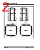

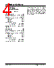

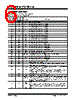

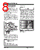

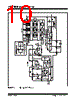

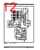
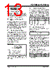
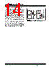
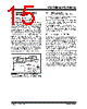
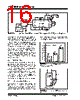

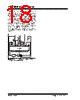

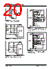
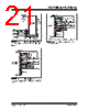
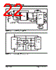

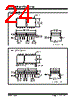
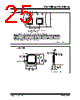


1. Overview & Purpose:
️· The document describes the TC7106A and TC7107A, which are dual-slope, integrating analog-to-digital converters (ADCs).
️· They are specifically designed to be used in systems requiring high accuracy and noise immunity.
️· The document explains how they work, their features, and how to interface them.
2. Dual Slope Conversion Principles (Section 3.1):
️· Dual Slope: The ADCs use a dual-slope conversion technique, involving two distinct phases: Signal Integration and Reference Voltage Integration (De-integration).
️· Benefits: Dual-slope converters are known for their accuracy and noise immunity. Noise is effectively averaged out during the integration periods.
️· Equation 3-1: Gives the relationship between the input signal, reference voltage, and integration time.
3. Analog Section (Section 4):
️· Auto-Zero Cycle: A crucial feature. It corrects for offset voltages in the circuit, ensuring high accuracy without needing external calibration. The cycle length is 1000-3000 counts.
️· Signal Integrate Cycle: The input signal is integrated for a fixed time.
️· Reference Integrate Phase: The integrator output returns to zero, and the time taken is proportional to the input signal.
️· Equation 4-2: Expresses the digital reading based on the integration times.
️· Common Mode Range: The differential input voltage must be within the device’s common mode range.
4. Digital Section (TC7106A):
️· Direct Drive: The TC7106A has built-in segment drivers for a 3-1/2 digit LCD.
️· Backplane Frequency: Controlled by an external clock, divided by 800.
️· AC Drive: The AC drive configuration minimizes DC voltage across LCD segments, extending display life.
️· TEST Pin: When pulled high, all segments are turned on, displaying -1888. *Warning: Do not leave the display in this mode for extended periods, as it can damage the LCD.*
️· Digital Ground: Generated internally, stabilizes the circuit.
5. Key Features and Equations:
️· Equation 3-1: V<sub>out</sub> = (V<sub>in</sub> * T<sub>SI</sub>) / T<sub>RI</sub> (Relates input signal, reference voltage, and integration times)
️· Equation 3-2: Explains the normal mode rejection.
️· Equation 4-1: Defines the signal integration period.
️· Equation 4-2: D = (T<sub>RI</sub> / T<sub>SI</sub>) * 1000 (Expresses the digital reading)
Important Notes/Warnings:
️· LCD Drive: The "TEST" pin should only be used for brief testing. Leaving the LCD in this state for a long time can damage it.
️· Common Mode Range: Ensure the input voltage falls within the specified common mode range for optimal performance.
️· Integration Period: The length of the integration period can be influenced by several factors.
This summary should give you a clear understanding of the information contained within the document. Let me know if you have any other questions.
1. Overview & Purpose:
️· The document describes the TC7106A and TC7107A, which are dual-slope, integrating analog-to-digital converters (ADCs).
️· They are specifically designed to be used in systems requiring high accuracy and noise immunity.
️· The document explains how they work, their features, and how to interface them.
2. Dual Slope Conversion Principles (Section 3.1):
️· Dual Slope: The ADCs use a dual-slope conversion technique, involving two distinct phases: Signal Integration and Reference Voltage Integration (De-integration).
️· Benefits: Dual-slope converters are known for their accuracy and noise immunity. Noise is effectively averaged out during the integration periods.
️· Equation 3-1: Gives the relationship between the input signal, reference voltage, and integration time.
3. Analog Section (Section 4):
️· Auto-Zero Cycle: A crucial feature. It corrects for offset voltages in the circuit, ensuring high accuracy without needing external calibration. The cycle length is 1000-3000 counts.
️· Signal Integrate Cycle: The input signal is integrated for a fixed time.
️· Reference Integrate Phase: The integrator output returns to zero, and the time taken is proportional to the input signal.
️· Equation 4-2: Expresses the digital reading based on the integration times.
️· Common Mode Range: The differential input voltage must be within the device’s common mode range.
4. Digital Section (TC7106A):
️· Direct Drive: The TC7106A has built-in segment drivers for a 3-1/2 digit LCD.
️· Backplane Frequency: Controlled by an external clock, divided by 800.
️· AC Drive: The AC drive configuration minimizes DC voltage across LCD segments, extending display life.
️· TEST Pin: When pulled high, all segments are turned on, displaying -1888. *Warning: Do not leave the display in this mode for extended periods, as it can damage the LCD.*
️· Digital Ground: Generated internally, stabilizes the circuit.
5. Key Features and Equations:
️· Equation 3-1: V<sub>out</sub> = (V<sub>in</sub> * T<sub>SI</sub>) / T<sub>RI</sub> (Relates input signal, reference voltage, and integration times)
️· Equation 3-2: Explains the normal mode rejection.
️· Equation 4-1: Defines the signal integration period.
️· Equation 4-2: D = (T<sub>RI</sub> / T<sub>SI</sub>) * 1000 (Expresses the digital reading)
Important Notes/Warnings:
️· LCD Drive: The "TEST" pin should only be used for brief testing. Leaving the LCD in this state for a long time can damage it.
️· Common Mode Range: Ensure the input voltage falls within the specified common mode range for optimal performance.
️· Integration Period: The length of the integration period can be influenced by several factors.
This summary should give you a clear understanding of the information contained within the document. Let me know if you have any other questions.
| Part No. | TC7106A |
| Manufacturer | MICROCHIP |
| Size | 534 Kbytes |
| Pages | 32 pages |
| Description | 3-1/2 Digit Analog-to-Digital Converters |
| Lei ha avuto il aiuto da alldatasheet? [ DONATE ] |
Di alldatasheet | Richest di pubblicita | contatti | Privacy Policy | Collegamento alla scheda tecnica | scambio Link | Ricerca produttore All Rights Reserved©Alldatasheet.com |
| Russian : Alldatasheetru.com | Korean : Alldatasheet.co.kr | Spanish : Alldatasheet.es | French : Alldatasheet.fr | Italian : Alldatasheetit.com Portuguese : Alldatasheetpt.com | Polish : Alldatasheet.pl | Vietnamese : Alldatasheet.vn Indian : Alldatasheet.in | Mexican : Alldatasheet.com.mx | British : Alldatasheet.co.uk | New Zealand : Alldatasheet.co.nz |
|
Family Site : ic2ic.com |
icmetro.com |
 Italian ▼
  English
 Chinese
 German
 Japanese
 Russian
 Korean
 Spanish
 French
 Portuguese
 Polish
 Vietnamese
 Indian
 Mexican
 British
 New Zealand