|
Motore di ricerca datesheet componenti elettronici |
|
|
Motore di ricerca datesheet componenti elettronici |
|
TC7106A Scheda tecnica(PDF) 16 Page - Microchip Technology |
|
|
|||||||||||||||||||||||||||||
TC7106A Scheda tecnica(HTML) 16 Page - Microchip Technology |
|
|
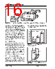
16 / 32 page  TC7106/A/TC7107/A DS21455C-page 16 © 2006 Microchip Technology Inc. FIGURE 8-2: Common Mode Voltage Removed in Battery Operation with VIN- = Analog Common The analog common pin serves to set the analog section reference or common point. The TC7106A is specifically designed to operate from a battery, or in any measure- ment system where input signals are not referenced (float), with respect to the TC7106A power source. The analog common potential of V+ – 3.0V gives a 6V end of battery life voltage. The common potential has a 0.001% voltage coefficient and a 15 Ω output impedance. With sufficiently high total supply voltage (V+ – V- > 7.0V), analog common is a very stable potential with excellent temperature stability, typically 20ppm/°C. This potential can be used to generate the reference voltage. An external voltage reference will be unneces- sary in most cases because of the 50ppm/°C maximum temperature coefficient. See Internal Voltage Reference discussion. 8.4 TEST (Pin 37) The TEST pin potential is 5V less than V+. TEST may be used as the negative power supply connection for external CMOS logic. The TEST pin is tied to the inter- nally generated negative logic supply (Internal Logic Ground) through a 500 Ω resistor in the TC7106A. The TEST pin load should be no more than 1mA. If TEST is pulled to V+ all segments plus the minus sign will be activated. Do not operate in this mode for more than several minutes with the TC7106A. With TEST = V+, the LCD segments are impressed with a DC voltage which will destroy the LCD. The TEST pin will sink about 10mA when pulled to V+. 8.5 Internal Voltage Reference The analog common voltage temperature stability has been significantly improved (Figure 8-3). The “A” version of the industry standard circuits allow users to upgrade old systems and design new systems without external voltage references. External R and C values do not need to be changed. Figure 8-4 shows analog common supplying the necessary voltage reference for the TC7106A/TC7107A. FIGURE 8-3: Analog Common Temperature Coefficient FIGURE 8-4: Internal Voltage Reference Connection VBUF CAZ VINT BP POL Segment Drive OSC1 OSC3 OSC2 V- V+ VREF+ VREF- Analog Common V- V+ V- V+ GND GND Measured System Power Source 9V LCD Display TC7106A + VIN- VIN+ Typical No Maximum Specified No Maximum Specified No Maximum Specified Typical Typical 200 180 160 140 120 100 80 60 40 20 0 ICL7136 TC 7106A ICL7106 Maximum Limit V- Analog Common TC7106A TC7107A VREF+ 32 35 36 24k Ω 1k Ω VREF- VREF 1 Set VREF = 1/2 VFULL SCALE V+ |
|
Link URL |
| Lei ha avuto il aiuto da alldatasheet? [ DONATE ] |
Di alldatasheet | Richest di pubblicita | contatti | Privacy Policy | Collegamento alla scheda tecnica | scambio Link | Ricerca produttore All Rights Reserved©Alldatasheet.com |
| Russian : Alldatasheetru.com | Korean : Alldatasheet.co.kr | Spanish : Alldatasheet.es | French : Alldatasheet.fr | Italian : Alldatasheetit.com Portuguese : Alldatasheetpt.com | Polish : Alldatasheet.pl | Vietnamese : Alldatasheet.vn Indian : Alldatasheet.in | Mexican : Alldatasheet.com.mx | British : Alldatasheet.co.uk | New Zealand : Alldatasheet.co.nz |
|
Family Site : ic2ic.com |
icmetro.com |
 Italian ▼
 English
 Chinese
 German
 Japanese
 Russian
 Korean
 Spanish
 French
 Italian
 Portuguese
 Polish
 Vietnamese
 Indian
 Mexican
 British
 New Zealand