 |
Motore di ricerca datesheet componenti elettronici |
|
|
Motore di ricerca datesheet componenti elettronici |
|
The question interval is too short.
Please try again in a few seconds.

Hello, Please ask a question about ASF130_17 Datasheet
# Example questions:
➢ What is the primary difference in the output power measurement setup between the performance tables in section 3 and section 4?
➢ What are the dimensions of the sot363 package?
➢ What is the gain of the asf130 at 1200 mhz with a supply voltage of +3v and a load impedance of 75 ohms?
| Part No. | ASF130_17 |
| Manufacturer | ASB |
| Size | 536 Kbytes |
| Pages | 11 pages |
| Description | Gain Block Amplifier MMIC over DC ~1000MHz |




1. General Overview & Key Features
️· Device: ASF130 MMIC (Monolithic Microwave Integrated Circuit) Amplifier
️· Application: Designed for CATV (Community Antenna Television) applications, specifically within the 50-1200 MHz frequency range, with a 75-ohm impedance.
️· Function: Low Noise Amplifier (LNA) – Amplifies signals while minimizing added noise.
️· Package: SOT363 (a small surface mount package: 2.1 x 2.0 x 1.0 mm)
️· Supply Voltage: +3 V
2. Electrical Characteristics (Two Configurations: 75-ohm and general)
️· Configuration 1: 75-ohm CATV Application
- Frequency Range: 50 – 1200 MHz
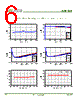
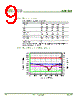
- Gain: 16.8 dB (at 50 MHz), 16.2 dB (at 500 MHz), 15.5 dB (at 1000 MHz), 14.9 dB (at 1200 MHz)
- Input Return Loss (S11): -10 dB (at 50 MHz), -12 dB (at 500 MHz), -12 dB (at 1000 MHz), -11 dB (at 1200 MHz)
- Output Return Loss (S22): -14 dB (at 50 MHz), -17 dB (at 500 MHz), -16 dB (at 1000 MHz), -12 dB (at 1200 MHz)
- Noise Figure: 2.7 dB (at 50 MHz), 2.9 dB (at 500 MHz), 3.0 dB (at 1000 MHz), 3.1 dB (at 1200 MHz)
- Output IP3 (Third-Order Intercept Point): 35.0 dBm (at 50 MHz), 32.0 dBm (at 500 MHz), 28.5 dBm (at 1000 MHz), 27.5 dBm (at 1200 MHz) – *Indicates the amplifier's linearity*
- Output IP2 (Second-Order Intercept Point): 53 dBm (at 50 MHz), 59 dBm (at 500 MHz), 51 dBm (at 1000 MHz), 49 dBm (at 1200 MHz) – *Also related to linearity*
- Output P1dB (1 dB Compression Point): 16.5 dBm (at 50 MHz), 17.0 dBm (at 500 MHz), 16.5 dBm (at 1000 MHz), 16.0 dBm (at 1200 MHz) – *Indicates where the amplifier starts to distort the signal*
- Supply Current: 53 mA
️· Configuration 2: General Application (details not fully provided in the supplied document)
3. Bill of Materials (Typical Application Circuit)
️· ASF130: MMIC Amplifier
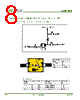
️· C1, C2: 10 nF DC blocking capacitors (Murata)
️· C3: 10 µF decoupling capacitor (Murata)
️· L1: 820 nH RF choke inductor (Samsung)
4. Application Notes & Layout Recommendations
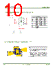
️· Ground Vias: Critical for both RF grounding and thermal management. Place them strategically under the ground leads and exposed pad.
️· Soldering Profile: Follow the recommended reflow profile for proper soldering.
️· Two-Tone Testing: IP3 and IP2 measurements are taken using two tones at a specific output power and frequency separation (6 MHz).
5. Package Outline
️· Detailed dimensions of the SOT363 package are provided.
6. Key Terminology
️· MMIC: A fully integrated circuit, containing multiple transistors and passive components on a single chip.
️· CATV: Community Antenna Television - system that distributes television signals.
️· S11: Input Return Loss. A measure of how much of the input signal is reflected back to the source. Lower (more negative) values are better.
️· S22: Output Return Loss. Similar to S11, but for the output. Lower (more negative) values are better.
️· Noise Figure (NF): A measure of how much noise is added by the amplifier. Lower values are better.
️· IP3: Third-Order Intercept Point. A measure of the amplifier's linearity. A higher IP3 indicates better linearity.
️· IP2: Second-Order Intercept Point. Another linearity measure, useful for identifying even-order distortion.
️· P1dB: 1 dB Compression Point. The output power at which the amplifier's gain is reduced by 1 dB due to non-linear effects.
Overall Summary:
The ASF130 is a low-noise amplifier designed for CATV applications, delivering good gain and linearity in a small package. The datasheet provides sufficient information to implement the amplifier effectively, including detailed electrical characteristics, a bill of materials, and layout recommendations.
1. General Overview & Key Features
️· Device: ASF130 MMIC (Monolithic Microwave Integrated Circuit) Amplifier
️· Application: Designed for CATV (Community Antenna Television) applications, specifically within the 50-1200 MHz frequency range, with a 75-ohm impedance.
️· Function: Low Noise Amplifier (LNA) – Amplifies signals while minimizing added noise.
️· Package: SOT363 (a small surface mount package: 2.1 x 2.0 x 1.0 mm)
️· Supply Voltage: +3 V
2. Electrical Characteristics (Two Configurations: 75-ohm and general)
️· Configuration 1: 75-ohm CATV Application
- Frequency Range: 50 – 1200 MHz
- Gain: 16.8 dB (at 50 MHz), 16.2 dB (at 500 MHz), 15.5 dB (at 1000 MHz), 14.9 dB (at 1200 MHz)
- Input Return Loss (S11): -10 dB (at 50 MHz), -12 dB (at 500 MHz), -12 dB (at 1000 MHz), -11 dB (at 1200 MHz)
- Output Return Loss (S22): -14 dB (at 50 MHz), -17 dB (at 500 MHz), -16 dB (at 1000 MHz), -12 dB (at 1200 MHz)
- Noise Figure: 2.7 dB (at 50 MHz), 2.9 dB (at 500 MHz), 3.0 dB (at 1000 MHz), 3.1 dB (at 1200 MHz)
- Output IP3 (Third-Order Intercept Point): 35.0 dBm (at 50 MHz), 32.0 dBm (at 500 MHz), 28.5 dBm (at 1000 MHz), 27.5 dBm (at 1200 MHz) – *Indicates the amplifier's linearity*
- Output IP2 (Second-Order Intercept Point): 53 dBm (at 50 MHz), 59 dBm (at 500 MHz), 51 dBm (at 1000 MHz), 49 dBm (at 1200 MHz) – *Also related to linearity*
- Output P1dB (1 dB Compression Point): 16.5 dBm (at 50 MHz), 17.0 dBm (at 500 MHz), 16.5 dBm (at 1000 MHz), 16.0 dBm (at 1200 MHz) – *Indicates where the amplifier starts to distort the signal*
- Supply Current: 53 mA
️· Configuration 2: General Application (details not fully provided in the supplied document)
3. Bill of Materials (Typical Application Circuit)
️· ASF130: MMIC Amplifier
️· C1, C2: 10 nF DC blocking capacitors (Murata)
️· C3: 10 µF decoupling capacitor (Murata)
️· L1: 820 nH RF choke inductor (Samsung)
4. Application Notes & Layout Recommendations
️· Ground Vias: Critical for both RF grounding and thermal management. Place them strategically under the ground leads and exposed pad.
️· Soldering Profile: Follow the recommended reflow profile for proper soldering.
️· Two-Tone Testing: IP3 and IP2 measurements are taken using two tones at a specific output power and frequency separation (6 MHz).
5. Package Outline
️· Detailed dimensions of the SOT363 package are provided.
6. Key Terminology
️· MMIC: A fully integrated circuit, containing multiple transistors and passive components on a single chip.
️· CATV: Community Antenna Television - system that distributes television signals.
️· S11: Input Return Loss. A measure of how much of the input signal is reflected back to the source. Lower (more negative) values are better.
️· S22: Output Return Loss. Similar to S11, but for the output. Lower (more negative) values are better.
️· Noise Figure (NF): A measure of how much noise is added by the amplifier. Lower values are better.
️· IP3: Third-Order Intercept Point. A measure of the amplifier's linearity. A higher IP3 indicates better linearity.
️· IP2: Second-Order Intercept Point. Another linearity measure, useful for identifying even-order distortion.
️· P1dB: 1 dB Compression Point. The output power at which the amplifier's gain is reduced by 1 dB due to non-linear effects.
Overall Summary:
The ASF130 is a low-noise amplifier designed for CATV applications, delivering good gain and linearity in a small package. The datasheet provides sufficient information to implement the amplifier effectively, including detailed electrical characteristics, a bill of materials, and layout recommendations.
| Part No. | ASF130_17 |
| Manufacturer | ASB |
| Size | 536 Kbytes |
| Pages | 11 pages |
| Description | Gain Block Amplifier MMIC over DC ~1000MHz |
| Lei ha avuto il aiuto da alldatasheet? [ DONATE ] |
Di alldatasheet | Richest di pubblicita | contatti | Privacy Policy | Collegamento alla scheda tecnica | scambio Link | Ricerca produttore All Rights Reserved©Alldatasheet.com |
| Russian : Alldatasheetru.com | Korean : Alldatasheet.co.kr | Spanish : Alldatasheet.es | French : Alldatasheet.fr | Italian : Alldatasheetit.com Portuguese : Alldatasheetpt.com | Polish : Alldatasheet.pl | Vietnamese : Alldatasheet.vn Indian : Alldatasheet.in | Mexican : Alldatasheet.com.mx | British : Alldatasheet.co.uk | New Zealand : Alldatasheet.co.nz |
|
Family Site : ic2ic.com |
icmetro.com |
 Italian ▼
  English
 Chinese
 German
 Japanese
 Russian
 Korean
 Spanish
 French
 Portuguese
 Polish
 Vietnamese
 Indian
 Mexican
 British
 New Zealand