|
Motore di ricerca datesheet componenti elettronici |
|
|
Motore di ricerca datesheet componenti elettronici |
|
LTC3405A-1.5 Scheda tecnica(PDF) 7 Page - Linear Technology |
|
|
|||||||||||||||||||||||||||||
LTC3405A-1.5 Scheda tecnica(HTML) 7 Page - Linear Technology |
|
|
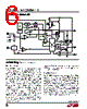
7 / 16 page  7 LTC3405A-1.5/LTC3405A-1.8 sn3405a1518 3405a1518fs OPERATIO (Refer to Functional Diagram) When the converter is in Burst Mode operation, the peak current of the inductor is set to approximately 100mA re- gardless of the output load. Each burst event can last from a few cycles at light loads to almost continuously cycling with short sleep intervals at moderate loads. In between these burst events, the power MOSFETs and any unneeded circuitry are turned off, reducing the quiescent current to 20 µA. In this sleep state, the load current is being supplied solely from the output capacitor. As the output voltage droops, the EA amplifier’s output rises above the sleep threshold signaling the BURST comparator to trip and turn the top MOSFET on. This process repeats at a rate that is dependent on the load demand. Short-Circuit Protection When the output is shorted to ground, the frequency of the oscillator is reduced to about 210kHz, 1/7 the nominal frequency. This frequency foldback ensures that the in- ductor current has more time to decay, thereby preventing runaway. The oscillator’s frequency will progressively increase to 1.5MHz when VOUT rises above 0V. Low Supply Operation The LTC3405A series parts will operate with input supply voltages as low as 2.5V, but the maximum allowable output current is reduced at this low voltage. Figure 2 shows the reduction in the maximum output current as a function of input voltage for both fixed output voltages. Figure 2. Maximum Output Current vs Input Voltage SUPPLY VOLTAGE (V) 2.5 600 500 400 300 200 100 0 3.0 3.5 4.0 4.5 3405A1518 F02 5.0 5.5 VOUT = 1.8V VOUT = 1.5V Slope Compensation and Inductor Peak Current Slope compensation provides stability in constant fre- quency architectures by preventing subharmonic oscilla- tions at high duty cycles. It is accomplished internally by adding a compensating ramp to the inductor current signal at duty cycles in excess of 40%. Normally, this results in a reduction of maximum inductor peak current for duty cycles > 40%. However, the LTC3405A series parts use a patent-pending scheme that counteracts this compensating ramp, which allows the maximum inductor peak current to remain unaffected throughout all duty cycles. |
|
|
Link URL |
| Lei ha avuto il aiuto da alldatasheet? [ DONATE ] |
Di alldatasheet | Richest di pubblicita | contatti | Privacy Policy | Collegamento alla scheda tecnica | scambio Link | Ricerca produttore All Rights Reserved©Alldatasheet.com |
| Russian : Alldatasheetru.com | Korean : Alldatasheet.co.kr | Spanish : Alldatasheet.es | French : Alldatasheet.fr | Italian : Alldatasheetit.com Portuguese : Alldatasheetpt.com | Polish : Alldatasheet.pl | Vietnamese : Alldatasheet.vn Indian : Alldatasheet.in | Mexican : Alldatasheet.com.mx | British : Alldatasheet.co.uk | New Zealand : Alldatasheet.co.nz |
|
Family Site : ic2ic.com |
icmetro.com |
 Italian ▼
 English
 Chinese
 German
 Japanese
 Russian
 Korean
 Spanish
 French
 Italian
 Portuguese
 Polish
 Vietnamese
 Indian
 Mexican
 British
 New Zealand