|
Motore di ricerca datesheet componenti elettronici |
|
|
Motore di ricerca datesheet componenti elettronici |
|
LTC3405A-1.5 Scheda tecnica(PDF) 9 Page - Linear Technology |
|
|
|||||||||||||||||||||||||||||
LTC3405A-1.5 Scheda tecnica(HTML) 9 Page - Linear Technology |
|
|
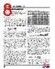
9 / 16 page  9 LTC3405A-1.5/LTC3405A-1.8 sn3405a1518 3405a1518fs APPLICATIO S I FOR ATIO where L1, L2, etc. are the individual losses as a percentage of input power. Although all dissipative elements in the circuit produce losses, two main sources usually account for most of the losses in LTC3405A series parts circuits: VIN quiescent current and I2R losses. The VIN quiescent current loss dominates the efficiency loss at very low load currents whereas the I2R loss dominates the efficiency loss at medium to high load currents. In a typical efficiency plot, the efficiency curve at very low load currents can be misleading since the actual power lost is of no conse- quence as illustrated in Figure 3. Aluminum electrolytic and dry tantalum capacitors are both available in surface mount configurations. In the case of tantalum, it is critical that the capacitors are surge tested for use in switching power supplies. An excellent choice is the AVX TPS series of surface mount tantalum. These are specially constructed and tested for low ESR so they give the lowest ESR for a given volume. Other capacitor types include Sanyo POSCAP, Kemet T510 and T495 series, and Sprague 593D and 595D series. Consult the manufacturer for other specific recommendations. Using Ceramic Input and Output Capacitors Higher values, lower cost ceramic capacitors are now becoming available in smaller case sizes. Their high ripple current, high voltage rating and low ESR make them ideal for switching regulator applications. Because the LTC3405A series’ control loop does not depend on the output capacitor’s ESR for stable operation, ceramic capacitors can be used freely to achieve very low output ripple and small circuit size. Care must be taken when ceramic capacitors are used at the input and the output. When a ceramic capacitor is used at the input and the power is supplied by a wall adapter through long wires, a load step at the output can induce ringing at the input, VIN. At best, this ringing can couple to the output and be mistaken as loop instability. At worst, a sudden inrush of current through the long wires can potentially cause a voltage spike at VIN, large enough to damage the part. When choosing the input and output ceramic capacitors, choose the X5R or X7R dielectric formulations. These dielectrics have the best temperature and voltage charac- teristics of all the ceramics for a given value and size. Efficiency Considerations The efficiency of a switching regulator is equal to the output power divided by the input power times 100%. It is often useful to analyze individual losses to determine what is limiting the efficiency and which change would produce the most improvement. Efficiency can be expressed as: Efficiency = 100% – (L1 + L2 + L3 + ...) Figure 3. Power Lost vs Load Current LOAD CURRENT (mA) 0.1 10 1000 1 0.1 0.01 0.001 0.0001 3405A1518 F03 1 100 VOUT = 1.8V VIN = 3.6V VOUT = 1.5V 1. The VIN quiescent current is due to two components: the DC bias current as given in the electrical character- istics and the internal main switch and synchronous switch gate charge currents. The gate charge current results from switching the gate capacitance of the internal power MOSFET switches. Each time the gate is switched from high to low to high again, a packet of charge, dQ, moves from VIN to ground. The resulting dQ/dt is the current out of VINthat is typically larger than the DC bias current. In continuous mode, IGATECHG = f(QT + QB) where QT and QB are the gate charges of the internal top and bottom switches. Both the DC bias and gate charge losses are proportional to VIN and thus their effects will be more pronounced at higher supply voltages. |
|
|
Link URL |
| Lei ha avuto il aiuto da alldatasheet? [ DONATE ] |
Di alldatasheet | Richest di pubblicita | contatti | Privacy Policy | Collegamento alla scheda tecnica | scambio Link | Ricerca produttore All Rights Reserved©Alldatasheet.com |
| Russian : Alldatasheetru.com | Korean : Alldatasheet.co.kr | Spanish : Alldatasheet.es | French : Alldatasheet.fr | Italian : Alldatasheetit.com Portuguese : Alldatasheetpt.com | Polish : Alldatasheet.pl | Vietnamese : Alldatasheet.vn Indian : Alldatasheet.in | Mexican : Alldatasheet.com.mx | British : Alldatasheet.co.uk | New Zealand : Alldatasheet.co.nz |
|
Family Site : ic2ic.com |
icmetro.com |
 Italian ▼
 English
 Chinese
 German
 Japanese
 Russian
 Korean
 Spanish
 French
 Italian
 Portuguese
 Polish
 Vietnamese
 Indian
 Mexican
 British
 New Zealand