|
Motore di ricerca datesheet componenti elettronici |
|
|
Motore di ricerca datesheet componenti elettronici |
|
ADL8143ACPZN-R7 Scheda tecnica(PDF) 14 Page - Analog Devices |
|
|
|||||||||||||||||||||||||||||
ADL8143ACPZN-R7 Scheda tecnica(HTML) 14 Page - Analog Devices |
|
|
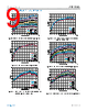
14 / 17 page  Data Sheet ADL8143 APPLICATIONS INFORMATION analog.com Rev. 0 | 14 of 17 The basic connections for operating the ADL8143 from 8 GHz to 14 GHz are shown in Figure 49. No external biasing inductor is required, allowing a 1.5 V supply to be connected to the VDD pin. It is recommended to use 0.1 µF and 100 pF power supply decoupling capacitors. The power supply decoupling capacitors shown in Figure 49 represent the configuration used to characterize and qualify the ADL8143. To set the IDQ, connect a resistor, R2, between the RBIAS and VDD pins. A default value of 487 Ω is recommended that results in a nominal IDQ of 35 mA. The RBIAS pin also draws a current that varies with the value of RBIAS. Table 8 and Table 9 show the recommended RBIAS values with the associated IDQ values. Do not leave the RBIAS pin open. Figure 49. Typical Application Circuit RECOMMENDED BIAS SEQUENCING The correct sequencing of the DC and RF power is required to safely operate the ADL8143. During power-up, apply VDD before the RF power is applied to RFIN, and during power-off, remove the RF power from RFIN before VDD is powered off. Table 8. Recommended Bias Resistor Values for Various IDQ Values, VDD = 1.5 V RBIAS (Ω) IDQ (mA) IDQ_AMP (mA) IRBIAS (mA) 1171 20 19.1 0.9 835 25 23.8 1.2 629 30 28.5 1.5 487 35 33.1 1.9 398 40 37.8 2.2 329 45 42.4 2.6 Table 9. Recommended Bias Resistor Values for Various Supply Voltages, IDQ = 35 mA RBIAS (Ω) VDD (V) 295 1.2 356 1.3 487 1.5 652 1.7 933 2.0 1494 2.5 2190 3.0 3091 3.5 |
|
|
Link URL |
| Lei ha avuto il aiuto da alldatasheet? [ DONATE ] |
Di alldatasheet | Richest di pubblicita | contatti | Privacy Policy | Collegamento alla scheda tecnica | scambio Link | Ricerca produttore All Rights Reserved©Alldatasheet.com |
| Russian : Alldatasheetru.com | Korean : Alldatasheet.co.kr | Spanish : Alldatasheet.es | French : Alldatasheet.fr | Italian : Alldatasheetit.com Portuguese : Alldatasheetpt.com | Polish : Alldatasheet.pl | Vietnamese : Alldatasheet.vn Indian : Alldatasheet.in | Mexican : Alldatasheet.com.mx | British : Alldatasheet.co.uk | New Zealand : Alldatasheet.co.nz |
|
Family Site : ic2ic.com |
icmetro.com |
 Italian ▼
 English
 Chinese
 German
 Japanese
 Russian
 Korean
 Spanish
 French
 Italian
 Portuguese
 Polish
 Vietnamese
 Indian
 Mexican
 British
 New Zealand