|
Motore di ricerca datesheet componenti elettronici |
|
|
Motore di ricerca datesheet componenti elettronici |
|
SC4518HEVB Scheda tecnica(PDF) 7 Page - Semtech Corporation |
|
|
|||||||||||||||||||||||||||||
SC4518HEVB Scheda tecnica(HTML) 7 Page - Semtech Corporation |
|
|
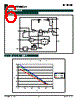
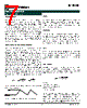
7 / 15 page  7 2007 Semtech Corp. www.semtech.com POWER MANAGEMENT SC4518H Application Information General Overview The SC4518H is a high frequency current mode buck PWM regulator. It has an internal clock with fixed- frequency. The SC4518H uses two feedback loops (voltage loop and current loop) that control the duty cycle of the internal power switch. The error amplifier functions like that of the voltage mode controller. The output of the error amplifier provides a switch current reference. This technique effectively removes one of the double poles in the output LC filter stage. With this, it is easier to compensate a current mode converter for better performance. A minimum 2.7V voltage is required to saturate the NPN power switch when it is ON to reduce its conduction loss. Current Limit and Over Current Protection The current sense amplifier in the SC4518H monitors the switch current during each cycle. Overcurrent protection (OCP) is triggered when the current limit exceeds the upper limit of 2A, detected by a voltage on COMP being greater than about 2V. When an OCP fault is detected, the switch is turned off and the external COMP capacitor is discharged at the rate of dv/dt = 3µA/ C comp. Once the COMP voltage has fallen below 250mV, the part enters a normal startup cycle. C comp is the total capacitance value attached to COMP. In the case of sustained overcurrent or dead-short, the part will continually cycle through the retry sequence as described above, at a rate dependent on the value of Ccomp. During start up, the voltage on COMP rises roughly at the rate of dv/dt = 120µA/C comp. Therefore, the retry time for a sustained overcurrent can be approximately calculated as: uA 3 V 2 C 120uA 2V C T comp comp retry • + • = Figure 1 shows the voltage on COMP during a sustained overcurrent condition. Figure 1. Voltage on COMP for Startup and OCP Enable Pulling and holding the EN pin below 0.4V activates the shut down mode of the SC4518H which reduces the input supply current to less than 150µA. During the shut down mode, the switch is turned off. The SC4518H is turned on if the EN pin is pulled high. Oscillator Its internal free running oscillator sets the PWM frequency at 600kHz for the SC4518H without any external components to program the frequency. An external clock with a duty cycle from 20% to 80% connected to the SYNC pin activates synchronous mode. The frequency of the external clock can be from 750kHz to 1.2MHz. UVLO When the EN pin is pulled and held above 1.8V, the voltage on Pin IN determines the operation of the SC4518H. As VIN increases during power up, the internal circuit senses VIN and keeps the power transistor off until VIN reaches 4.4V. Load Current The peak current I PEAK in the switch is internally limited. For a specific application, the allowed load current I OMAX will change if the input voltage drifts away from the original design as given for continuous current mode: s O OMAX f L 2 ) D 1 ( V 2 I ⋅ ⋅ − ⋅ − = Where: fs = switching frequency, Vo = output voltage and D = duty ratio, VO/VI V I = input voltage. Figure 2 shows the theoretical maximum load current for the specific cases. In a real application, however, the allowed maximum load current also depends on the layout and the air cooling condition. Therefore, the maximum load current may need to be derated according to the thermal situation of the application. |
|
|
Link URL |
| Lei ha avuto il aiuto da alldatasheet? [ DONATE ] |
Di alldatasheet | Richest di pubblicita | contatti | Privacy Policy | Collegamento alla scheda tecnica | scambio Link | Ricerca produttore All Rights Reserved©Alldatasheet.com |
| Russian : Alldatasheetru.com | Korean : Alldatasheet.co.kr | Spanish : Alldatasheet.es | French : Alldatasheet.fr | Italian : Alldatasheetit.com Portuguese : Alldatasheetpt.com | Polish : Alldatasheet.pl | Vietnamese : Alldatasheet.vn Indian : Alldatasheet.in | Mexican : Alldatasheet.com.mx | British : Alldatasheet.co.uk | New Zealand : Alldatasheet.co.nz |
|
Family Site : ic2ic.com |
icmetro.com |
 Italian ▼
 English
 Chinese
 German
 Japanese
 Russian
 Korean
 Spanish
 French
 Italian
 Portuguese
 Polish
 Vietnamese
 Indian
 Mexican
 British
 New Zealand