|
Motore di ricerca datesheet componenti elettronici |
|
|
Motore di ricerca datesheet componenti elettronici |
|
SC4518HEVB Scheda tecnica(PDF) 9 Page - Semtech Corporation |
|
|
|||||||||||||||||||||||||||||
SC4518HEVB Scheda tecnica(HTML) 9 Page - Semtech Corporation |
|
|
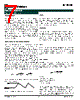
9 / 15 page  9 2007 Semtech Corp. www.semtech.com POWER MANAGEMENT SC4518H Input Capacitor Selection The input capacitor selection is based on its ripple current level, required capacitance and voltage rating. This capacitor must be able to provide the ripple current by the switching actions. For the continuous conduction mode, the RMS value of the input capacitor current I CIN(RMS) can be calculated from: I 2 O I O OMAX ) RMS ( CIN V ) V V ( V I I − ⋅ ⋅ = This current gives the capacitor’s power loss through its R CIN(ESR) as follows: ) ESR ( CIN ) RMS ( CIN 2 CIN R I P • = The input ripple voltage mainly depends on the input capacitor’s ESR and its capacitance for a given load, input voltage and output voltage. Assuming that the input current of the converter is constant, the required input capacitance for a given voltage ripple can be calculated by: ) R I V ( fs ) D 1 ( D I C ) ESR ( CIN OMAX I OMAX IN ⋅ − ∆ ⋅ − ⋅ ⋅ = Where: ∆V I = the given input voltage ripple. Because the input capacitor is exposed to the large surge current, attention is needed for the input capacitor. If tantalum capacitors are used at the input side of the converter, one needs to ensure that the RMS and surge ratings are not exceeded. For generic tantalum capacitors, it is suggested to derate their voltage ratings at a ratio of about two to protect these input capacitors. Boost Capacitor and its Supply Source Selection The boost capacitor selection is based on its discharge ripple voltage, worst case conduction time and boost current. The worst case conduction time T w can be estimated as follows: max s W D f 1 T ⋅ = Where: f s = the switching frequency and Dmax = maximum duty ratio, 0.85 for the SC4518H. The required minimum capacitance for the boost capacitor will be: W D B boost T V I C ⋅ = Where: I B = the boost current and V D= discharge ripple voltage. With f s = 600kHz, VD = 0.5V and IB =0.045A, the required minimum capacitance for the boost capacitor is: nF 128 85 . 0 k 600 1 5 . 0 045 . 0 D f 1 V I C max s D B boost = ⋅ ⋅ = ⋅ ⋅ = The internal driver of the switch requires a minimum 2.7V to fully turn on that switch to reduce its conduction loss. If the output voltage is less than 2.7V, the boost capacitor can be connected to either the input side or an independent supply with a decoupling capacitor. But the Pin BST should not see a voltage higher than its maximum rating. Freewheeling Diode Selection This diode conducts during the switch’s off-time. The diode should have enough current capability for full load and short circuit conditions without any thermal concerns. Its maximum repetitive reverse block voltage has to be higher than the input voltage of the SC4518H. A low forward conduction drop is also required to increase the overall efficiency. The freewheeling diode should be turned on and off fast with minimum reverse recovery because the SC4518H is designed for high frequency applications. SS13 Schottky rectifier is recommended for certain applications. The average current of the diode, I D_AVG can be calculated by: ) D 1 ( I I max O AVG _ D − ⋅ = Thermal Considerations There are three major power dissipation sources for the SC4518H. The internal switch conduction loss, its switching loss due to the high frequency switching actions and the base drive boost circuit loss. These losses can be estimated as: ) V ( D I 500 10 V I 10 8 . 10 D R I P boost o I o 3 on 2 o total ⋅ ⋅ ⋅ + ⋅ ⋅ ⋅ + ⋅ ⋅ = − Application Information (Cont.) |
|
|
Link URL |
| Lei ha avuto il aiuto da alldatasheet? [ DONATE ] |
Di alldatasheet | Richest di pubblicita | contatti | Privacy Policy | Collegamento alla scheda tecnica | scambio Link | Ricerca produttore All Rights Reserved©Alldatasheet.com |
| Russian : Alldatasheetru.com | Korean : Alldatasheet.co.kr | Spanish : Alldatasheet.es | French : Alldatasheet.fr | Italian : Alldatasheetit.com Portuguese : Alldatasheetpt.com | Polish : Alldatasheet.pl | Vietnamese : Alldatasheet.vn Indian : Alldatasheet.in | Mexican : Alldatasheet.com.mx | British : Alldatasheet.co.uk | New Zealand : Alldatasheet.co.nz |
|
Family Site : ic2ic.com |
icmetro.com |
 Italian ▼
 English
 Chinese
 German
 Japanese
 Russian
 Korean
 Spanish
 French
 Italian
 Portuguese
 Polish
 Vietnamese
 Indian
 Mexican
 British
 New Zealand