|
Motore di ricerca datesheet componenti elettronici |
|
|
Motore di ricerca datesheet componenti elettronici |
|
ISL73006SLHDEMO2Z Scheda tecnica(PDF) 24 Page - Renesas Technology Corp |
|
|
|||||||||||||||||||||||||||||
ISL73006SLHDEMO2Z Scheda tecnica(HTML) 24 Page - Renesas Technology Corp |
|
|
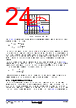
24 / 31 page  R34DS0034EU0101 Rev.1.01 Page 24 Mar 13, 2024 ISL73006SLH Datasheet Use Equation 12 to approximate the amplitudes of the voltage spikes caused by capacitor ESR and ESL, where ITRAN = Output load current transient.: In a typical converter design, the ESR of the output capacitor bank impacts the transient response. The ESR and the ESL determine the number and types of output capacitors required to minimize the initial voltage spike at the output transient response. It may be necessary to place multiple output capacitors of both ceramic (to provide low ESR, ESL) and Tantalum (to provide the bulk capacitance in a small footprint) types in parallel to reduce the parasitic ESR and ESL to achieve minimize the magnitude of the output voltage spike during a load transient response. The ESL of the capacitor is an important parameter and not usually listed in datasheets. You can use Equation 13 to approximate ESL if an Impedance vs Frequency curve is available, where fres is the frequency where the lowest impedance is achieved (resonant frequency). The ESL of the capacitor becomes a concern when designing circuits that supply power to loads with high rates of change in the current. If ΔVDIP and/or ΔVPEAK is too large for the output voltage limits, you may need to increase the capacitance. A trade-off between output inductance and output capacitance may be necessary in this situation. 5.16 Output Inductor Selection The inductor value determines the ripple current of the converter. Choosing an inductor current requires a somewhat arbitrary choice of ripple current, ∆I. A reasonable starting point is ~33% of the total load current. The output inductor influences the response time of the regulator to a load transient. A smaller inductance value improves transient response but increases output voltage ripple. The inductor value determines the inductor ripple current, with the output voltage ripple being a function of the ripple current. Use Equation 14 to approximate the Figure 41. Typical Transient Response (EQ. 12) (EQ. 13) VOUT IOUT ΔVESL ΔVESR ΔVDIP ΔVPEAK ITRAN V ESR ESR ITRAN = VESL ESL dITRAN dt --------------------- = ESL 1 C2 f res 2 ------------------------------------------ = |
|
Link URL |
| Lei ha avuto il aiuto da alldatasheet? [ DONATE ] |
Di alldatasheet | Richest di pubblicita | contatti | Privacy Policy | Collegamento alla scheda tecnica | scambio Link | Ricerca produttore All Rights Reserved©Alldatasheet.com |
| Russian : Alldatasheetru.com | Korean : Alldatasheet.co.kr | Spanish : Alldatasheet.es | French : Alldatasheet.fr | Italian : Alldatasheetit.com Portuguese : Alldatasheetpt.com | Polish : Alldatasheet.pl | Vietnamese : Alldatasheet.vn Indian : Alldatasheet.in | Mexican : Alldatasheet.com.mx | British : Alldatasheet.co.uk | New Zealand : Alldatasheet.co.nz |
|
Family Site : ic2ic.com |
icmetro.com |
 Italian ▼
 English
 Chinese
 German
 Japanese
 Russian
 Korean
 Spanish
 French
 Italian
 Portuguese
 Polish
 Vietnamese
 Indian
 Mexican
 British
 New Zealand