|
Motore di ricerca datesheet componenti elettronici |
|
|
Motore di ricerca datesheet componenti elettronici |
|
PA241CE Scheda tecnica(PDF) 5 Page - Cirrus Logic |
|
|
|||||||||||||||||||||||||||||
PA241CE Scheda tecnica(HTML) 5 Page - Cirrus Logic |
|
|
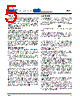
5 / 7 page  PA241 PA241U 5 P r o d u c t I n n o v a t i o n F r o m GENERAL Please read Application Note 1 "General Operating Consid- erations" which covers stability, power supplies, heat sinking, mounting, current limit, SOA interpretation, and specification interpretation. Visit www.Cirrus.com for design tools that help automate tasks such as calculations for stability, internal power dissipation, current limit, heat sink selection, Apex Precision Power's complete Application Notes library, Technical Seminar Workbook and Evaluation Kits. PHASECOMPENSATION Open loop gain and phase shift both increase with increas- ing temperature. The PHASE COMPENSATION typical graph shows closed loop gain and phase compensation capacitor value relationships for four case temperatures.The curves are based on achieving a phase margin of 50°. Calculate the high- est case temperature for the application (maximum ambient temperature and highest internal power dissipation) before choosing the compensation. Keep in mind that when working with small values of compensation, parasitics may play a large role in performance of the finished circuit. The compensation capacitor must be rated for at least the total voltage applied to the amplifier and should be a temperature stable type such as NPO or COG. OTHERSTABILITYCONCERNS There are two important concepts about closed loop gain when choosing compensation. They stem from the fact that while "gain" is the most commonly used term, β (the feedback factor) is really what counts when designing for stability. 1. Gain must be calculated as a non-inverting circuit (equal input and feedback resistors can provide a signal gain of -1, but for calculating offset errors, noise, and stability, this is a gain of 2). 2. Including a feedback capacitor changes the feedback factor or gain of the circuit. Consider Rin=4.7k, Rf=47k for a gain of 11. Compensation of 4.7 to 6.8pF would be reasonable. Adding 33pF parallel to the 47k rolls off the circuit at 103kHz, and at 2MHz has reduced gain from 11 to roughly 1.5 and the circuit is likely to oscillate. As a general rule the DC summing junction impedance (parallel combination of the feedback resistor and all input resistors) should be limited to 5k ohms or less. The amplifier input capacitance of about 6pF, plus capacitance of connecting traces or wires and (if used) a socket will cause undesirable circuit performance and even oscillation if these resistances are too high. In circuits requiring high resistances, measure or estimate the total sum point capacitance, multiply by Rin/Rf, and parallel Rf with this value. Capacitors included for this purpose are usually in the single digit pF range. This technique results in equal feedback factor calculations for AC and DC cases. It does not produce a roll off, but merely keeps β constant over a wide frequency range. Paragraph 6 of Application Note 19 details suitable stability tests for the finished circuit. CURRENTLIMIT For proper operation, the current limit resistor, Rcl, must be connected as shown in the external connection diagram. The minimum value is 3.9 ohms, however for optimum reliability, the resistor should be set as high as possible. The maximum practical value is 110 ohms. Current limit values can be pre- dicted as follows: Ilimit = Vbe Rcl Where Vbe is shown in the CURRENT LIMIT typical graph. Note that +Vbe should be used to predict current through the +Vs pin, -Vbe for current through the -Vs pin, and that they vary with case temperature. Value of the current limit resistor at a case temperature of 25° can be estimated as follows: Rcl = 0.7 Ilimit When the amplifier is current limiting, there may be spurious oscillation present during the current limited portion of the nega- tive half cycle.The frequency of the oscillation is not predictable and depends on the compensation, gain of the amplifier, value of the current limit resistor, and the load. The oscillation will cease as the amplifier comes out of current limit. SAFEOPERATINGAREA The MOSFET output stage of the PA241 is not limited by second breakdown considerations as in bipolar output stages. However there are still three distinct limitations: 1. Voltage withstand capability of the transistors. 2. Current handling capability of the die metalization. 3. Temperature of the output MOSFETS. These limitations can be seen in the SOA (see Safe Operat- ing Area graphs). Note that each pulse capability line shows a constant power level (unlike second breakdown limitations where power varies with voltage stress).These lines are shown for a case temperature of 25°C and correspond to thermal resistances of 5.2°C/W for the PA241CE and DF and 10.4°C/W for the PA241DW respectively. Pulse stress levels for other case temperatures can be calculated in the same manner as DC power levels at different temperatures. The output stage is protected against transient flyback by the parasitic diodes of the output stage MOSFET structure. However, for protection against sustained high energy flyback external fast-recovery diodes must be used. HEATSINKING The PA241DF package has a large exposed integrated copper heatslug to which the monolithic amplifier is directly attached.The solder connection of the heatslug to a minimum of 1 square inch foil area on the printed circuit board will result in thermal performance of 25°C/W junction to air rating of the PA241DF. Solder connection to an area of 1 to 2 square inches is recommended. This may be adequate heatsinking but the large number of variables involved suggest temperature mea- surements be made on the top of the package. Do not allow the temperature to exceed 85°C. |
|
|
Link URL |
| Lei ha avuto il aiuto da alldatasheet? [ DONATE ] |
Di alldatasheet | Richest di pubblicita | contatti | Privacy Policy | Collegamento alla scheda tecnica | scambio Link | Ricerca produttore All Rights Reserved©Alldatasheet.com |
| Russian : Alldatasheetru.com | Korean : Alldatasheet.co.kr | Spanish : Alldatasheet.es | French : Alldatasheet.fr | Italian : Alldatasheetit.com Portuguese : Alldatasheetpt.com | Polish : Alldatasheet.pl | Vietnamese : Alldatasheet.vn Indian : Alldatasheet.in | Mexican : Alldatasheet.com.mx | British : Alldatasheet.co.uk | New Zealand : Alldatasheet.co.nz |
|
Family Site : ic2ic.com |
icmetro.com |
 Italian ▼
 English
 Chinese
 German
 Japanese
 Russian
 Korean
 Spanish
 French
 Italian
 Portuguese
 Polish
 Vietnamese
 Indian
 Mexican
 British
 New Zealand