|
Motore di ricerca datesheet componenti elettronici |
|
|
Motore di ricerca datesheet componenti elettronici |
|
MPQ8632-8 Scheda tecnica(PDF) 20 Page - Monolithic Power Systems |
|
|
|||||||||||||||||||||||||||||
MPQ8632-8 Scheda tecnica(HTML) 20 Page - Monolithic Power Systems |
|
|
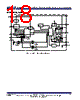
20 / 46 page  MPQ8632 HIGH EFFICIENCY 18V SYNCHRONOUS STEP-DOWN CONVERTER FAMILY FOR 4A TO 20A MPQ8632 Rev.1.24 www.MonolithicPower.com 20 8/28/2013 MPS Proprietary Information. Patent Protected. Unauthorized Photocopy and Duplication Prohibited. © 2013 MPS. All Rights Reserved. As the output current increases from the light load condition, the current modulator regulates the operating period that becomes shorter. The HS-FET turns ON more frequently. Hence, the switching frequency increases correspondingly. The output current reaches the critical level when the current modulator time decreases to zero. Determine the critical output current level as follows: IN SW OUT OUT IN OUT V F L 2 V ) V V ( I (2) Where FSW is the switching frequency. The IC turns into PWM mode once the output current exceeds the critical level. After that, the switching frequency stays fairly constant over the output current range. Switching Frequency Selecting the switching frequency requires trading off between efficiency and component size. Low frequency operation increases efficiency by reducing MOSFET switching losses, but requires larger inductor and capacitor values to minimize the output voltage ripple. For MPQ8632,set the on time using the FREQ pin to set the frequency for steady state operation at CCM. The MPQ8632 uses adaptive constant-on-time (COT) control, though the IC lacks a dedicated oscillator. Connect the FREQ pin to the IN pin through the resistor (RFREQ) so that the input voltage is feed-forwarded to the one-shot on-time timer. When operating in steady state at CCM, the duty ratio stays at VOUT/VIN, so the switching frequency is fairly constant over the input voltage range. Set the switching frequency as follows: 6 SW FREQ IN DELAY IN OUT 10 F (kHz) 6.1 R (k ) V (V) T (ns) V (V) 0.4 V (V) (3) Where TDELAY is the comparator delay of about 5ns. Typically, the MPQ8632 is set to 200kHz to 1MHz applications. It is optimized to operate at high switching frequencies at high efficiency: high switching frequencies allow for physically smaller LC filter components to reduce the PCB footprint. Jitter and FB Ramp Slope Figure 4 and Figure 5 show jitter occurring in both PWM mode and skip mode. When there is noise on the VFB descending slope, the HS-FET ON time deviates from its intended point and produces jitter and influences system stability. The VFB ripple’s slope steepness dominates the noise immunity though its magnitude has no direct effect. Figure 4 —Jitter in PWM Mode Figure 5 —Jitter in Skip Mode Ramp with a Large ESR Capacitor Using POSCAPs or other large-ESR capacitors as the output capacitor results in the ESR ripple dominating the output ripple. The ESR also significantly influences the VFB slope. Figure 6 shows the simplified equivalent circuit in PWM mode with the HS-FET off and without an external ramp circuit. |
|
Link URL |
| Lei ha avuto il aiuto da alldatasheet? [ DONATE ] |
Di alldatasheet | Richest di pubblicita | contatti | Privacy Policy | Collegamento alla scheda tecnica | scambio Link | Ricerca produttore All Rights Reserved©Alldatasheet.com |
| Russian : Alldatasheetru.com | Korean : Alldatasheet.co.kr | Spanish : Alldatasheet.es | French : Alldatasheet.fr | Italian : Alldatasheetit.com Portuguese : Alldatasheetpt.com | Polish : Alldatasheet.pl | Vietnamese : Alldatasheet.vn Indian : Alldatasheet.in | Mexican : Alldatasheet.com.mx | British : Alldatasheet.co.uk | New Zealand : Alldatasheet.co.nz |
|
Family Site : ic2ic.com |
icmetro.com |
 Italian ▼
 English
 Chinese
 German
 Japanese
 Russian
 Korean
 Spanish
 French
 Italian
 Portuguese
 Polish
 Vietnamese
 Indian
 Mexican
 British
 New Zealand