|
Motore di ricerca datesheet componenti elettronici |
|
|
Motore di ricerca datesheet componenti elettronici |
|
MPQ8632-20 Scheda tecnica(PDF) 10 Page - Monolithic Power Systems |
|
|
|||||||||||||||||||||||||||||
MPQ8632-20 Scheda tecnica(HTML) 10 Page - Monolithic Power Systems |
|
|
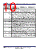
10 / 46 page  MPQ8632 HIGH EFFICIENCY 18V SYNCHRONOUS STEP-DOWN CONVERTER FAMILY FOR 4A TO 20A MPQ8632 Rev.1.24 www.MonolithicPower.com 10 8/28/2013 MPS Proprietary Information. Patent Protected. Unauthorized Photocopy and Duplication Prohibited. © 2013 MPS. All Rights Reserved. PIN FUNCTIONS MPQ8632GLE-4, MPQ8632GLE-6, MPQ8632GLE-8, MPQ8632GLE-10, MPQ8632HGLE-10, MPQ8632GLE-12 PIN # Name Description 1 EN Enable. Digital input that turns the regulator on or off. Drive EN high to turn on the regulator, drive it low to turn it off. Connect EN to IN through a pull-up resistor or a resistive voltage divider for automatic startup. Do not float this pin. 2 FREQ Frequency Set. Require a resistor connected between FREQ and IN to set the switching frequency. The input voltage and the resistor connected to the FREQ pin determine the ON time. The connection to the IN pin provides line feed-forward and stabilizes the frequency during input voltage’s variation. 3 FB Feedback. Connect to the tap of an external resistor divider from the output to GND to set the output voltage. FB is also configured to realize over-voltage protection (OVP) by monitoring output voltage. MPQ8632 and MPQ8632H provide different OVP mode. Please refer to the section “Over-Voltage-Protection (OVP)”. Place the resistor divider as close to FB pin as possible. Avoid using vias on the FB traces. 4 SS Soft Start. Connect an external capacitor to program the soft start time for the switch mode regulator. 5 AGND Analog ground. The control circuit reference. 6 PG Power Good. The output is an open drain signal. Require a pull-up resistor to a DC voltage to indicate high if the output voltage exceeds 91% of the nominal voltage. There is a delay from FB ≥ 91% to PG goes high. 7 VCC Internal 4.8V LDO Output. Power the driver and control circuits. 5V external bias can disable the internal LDO. Decouple with a ≥ 1µF ceramic capacitor as close to the pin as possible. For best results, use X7R or X5R dielectric ceramic capacitors for their stable temperature characteristics. 8 BST Bootstrap. Require a capacitor connected between SW and BST pins to form a floating supply across the high-side switch driver. 9, 14 IN Supply Voltage. Supply power to the internal MOSFET and regulator. The MPQ8632 operates from a +2.5V to +18V input rail with 5V external bias and a +4.5V to +18V input rail with internal bias. Require an input decoupling capacitor. Connect using wide PCB traces and multiple vias. 10-13 PGND System Ground. Reference ground of the regulated output voltage. PCB layout requires extra care. Connect using wide PCB traces. 15, 16 SW Switch Output. Connect to the inductor and bootstrap capacitor. The high-side switch drives the pin up to the VIN during the PWM duty cycle’s ON time. The inductor current drives the SW pin negative during the OFF-time. The low-side switch ’s ON-resistance and the internal Schottky diode clamp the negative voltage. Connect using wide PCB traces. |
|
Link URL |
| Lei ha avuto il aiuto da alldatasheet? [ DONATE ] |
Di alldatasheet | Richest di pubblicita | contatti | Privacy Policy | Collegamento alla scheda tecnica | scambio Link | Ricerca produttore All Rights Reserved©Alldatasheet.com |
| Russian : Alldatasheetru.com | Korean : Alldatasheet.co.kr | Spanish : Alldatasheet.es | French : Alldatasheet.fr | Italian : Alldatasheetit.com Portuguese : Alldatasheetpt.com | Polish : Alldatasheet.pl | Vietnamese : Alldatasheet.vn Indian : Alldatasheet.in | Mexican : Alldatasheet.com.mx | British : Alldatasheet.co.uk | New Zealand : Alldatasheet.co.nz |
|
Family Site : ic2ic.com |
icmetro.com |
 Italian ▼
 English
 Chinese
 German
 Japanese
 Russian
 Korean
 Spanish
 French
 Italian
 Portuguese
 Polish
 Vietnamese
 Indian
 Mexican
 British
 New Zealand