|
Motore di ricerca datesheet componenti elettronici |
|
|
Motore di ricerca datesheet componenti elettronici |
|
TC7107 Scheda tecnica(PDF) 14 Page - Microchip Technology |
|
|
|||||||||||||||||||||||||||||
TC7107 Scheda tecnica(HTML) 14 Page - Microchip Technology |
|
|
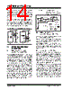
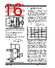
14 / 26 page  TC7106/A/TC7107/A DS21455B-page 14 © 2002 Microchip Technology Inc. Thedifferential reference canalsobe usedwhenadig- ital zero reading is required when VIN is not equal to zero. This is common in temperature measuring instru- mentation. A compensating offset voltage can be applied between analog common and VIN-. The trans- ducer output is connected between VIN+ and analog common. The internal voltage reference potential available at analog common will normally be used to supply the converter's reference. This potential is stable when- ever the supply potential is greater than approximately 7V. In applications where an externally generated ref- erence voltage is desired, refer to Figure 7-1. FIGURE 7-1: EXTERNAL REFERENCE 8.0 DEVICE PIN FUNCTIONAL DESCRIPTION 8.1 Differential Signal Inputs VIN+(Pin31), VIN-(Pin 30) The TC7106A/7017A is designed with true differential inputs and accepts input signals within the input stage common mode voltage range (VCM). The typical range is V+ – 1.0 to V+ + 1V. Common mode voltages are removed from the system when the TC7106A/ TC7107A operates from a battery or floating power source (isolated from measured system) and VIN-is connected to analog common (VCOM) (see Figure 8-2). In systems where Common mode voltages exist, the 86dB Common mode rejection ratio minimizes error. Common mode voltages do, however, affect the inte- grator output level. Integrator output saturation must be prevented. A worst case condition exists if a large pos- itive VCM exists in conjunction with a full scale negative differential signal. The negative signal drives the inte- grator output positive along with VCM (see Figure 8-1). For such applications the integrator output swing can be reduced below the recommended 2.0V full scale swing. The integrator output will swing within 0.3V of V+ or V- without increasing linearity errors. FIGURE 8-1: COMMON MODE VOLTAGE REDUCES AVAILABLE INTEGRATOR SWING (VCOM ≠ VIN) 8.2 Differential Reference VREF+(Pin36), VREF-(Pin 35) The reference voltage can be generated anywhere within the V+ to V- power supply range. To prevent rollover type errors being induced by large Common mode voltages, CREF should be large com- pared to stray node capacitance. The TC7106A/TC7107A circuits have a significantly lower analog common temperature coefficient. This gives a very stable voltage suitable for use as a refer- ence. The temperature coefficient of analog common is 20ppm/°C typically. 8.3 Analog Common(Pin32) The analog common pin is set at a voltage potential approximately 3.0V below V+. The potential is between 2.7V and 3.35V below V+. Analog common is tied inter- nally to the N channel FET capable of sinking 20mA. This FET will hold the common line at 3.0V should an external load attempt to pull the common line toward V+. Analog common source current is limited to 10 µA. Analog common is, therefore, easily pulled to a more negative voltage (i.e., below V+ – 3.0V). The TC7106A connects the internal VIN+and VIN- inputs to analog common during the auto-zero cycle. During the reference integrate phase, VIN- is con- nected to analog common. If VIN- is not externally con- nected to analog common, a Common mode voltage exists. This is rejected by the converter's 86dB Com- mon mode rejection ratio. In battery operation, analog common and VIN- are usually connected, removing Common mode voltage concerns. In systems where V- is connected to the power supply ground, or to a given voltage, analog common should be connected to VIN-. TC7106A TC7107A 6.8V Zener IZ V+ V+ V+ 1.2V Ref Common TC7106A TC7107A 6.8k Ω 20k Ω VREF+ VREF- VREF+ VREF- (a)(b) V+ RI + – VIN VCM CI Integrator VI = [ [ VCM – VIN Input Buffer CI = Integration Capacitor RI = Integration Resistor 4000 FOSC TI = Integration Time = Where: VI – + – + TI RI CI |
|
Link URL |
| Lei ha avuto il aiuto da alldatasheet? [ DONATE ] |
Di alldatasheet | Richest di pubblicita | contatti | Privacy Policy | Collegamento alla scheda tecnica | scambio Link | Ricerca produttore All Rights Reserved©Alldatasheet.com |
| Russian : Alldatasheetru.com | Korean : Alldatasheet.co.kr | Spanish : Alldatasheet.es | French : Alldatasheet.fr | Italian : Alldatasheetit.com Portuguese : Alldatasheetpt.com | Polish : Alldatasheet.pl | Vietnamese : Alldatasheet.vn Indian : Alldatasheet.in | Mexican : Alldatasheet.com.mx | British : Alldatasheet.co.uk | New Zealand : Alldatasheet.co.nz |
|
Family Site : ic2ic.com |
icmetro.com |
 Italian ▼
 English
 Chinese
 German
 Japanese
 Russian
 Korean
 Spanish
 French
 Italian
 Portuguese
 Polish
 Vietnamese
 Indian
 Mexican
 British
 New Zealand