|
Motore di ricerca datesheet componenti elettronici |
|
|
Motore di ricerca datesheet componenti elettronici |
|
STEC01 Scheda tecnica(PDF) 9 Page - STMicroelectronics |
|
|
|||||||||||||||||||||||||||||
STEC01 Scheda tecnica(HTML) 9 Page - STMicroelectronics |
|
|
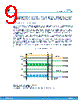
9 / 22 page  The typical example of RTPF calculation to obtain T1=6 minutes (3600 s): select the x256 pre-scaler (according to the ranges reported in Figure 5. Timer configuration truth table, by keeping T1P1 floating and T1P2=1. Divide 3600 s by selected pre-scaler value (256) and obtain 14.06 s that in the graph above corresponds to RTPF = 280 kΩ. 6.2 Timer expiration: normal mode Figure 7. Normal power cycle shows a typical power cycle not triggering a fault condition. In this example a PWM signal with duty cycle lower than 100% is applied to also show T2 timer functionality but a 100% duty cycle can be used as well. When a rising edge on the PWM input pin is detected (a), T1 is started, the internal power MOSFET is turned on and the external gate drive pin is activated. As soon as a falling edge of the PWM signal is detected, T2 is started. The purpose of T2 is to detect the end of the power cycle. After the power cycle starts, every high level of the PWM signal resets T2. If the PWM signal is in line with requirements (4 Hz < fPWM <5 kHz, duty cycle >30%), its low time is always lower than 285 ms (typ., T2 fixed value) and T2 never expires till the end of the power cycle (b). T2 is started and reset at each PWM period. After the power cycles ends, the voltage at PWM input remains low for more than 285 ms causing the expiration of T2 (c). When T2 expires, the internal N-channel power MOSFET is turned off, the GDRV output is deactivated and the device enters idle mode (low power consumption mode) during which it keeps monitoring the PWM line waiting for a new cycle to start. In this example the time duration of the full power cycle (a to c) is lower than the maximum on-time programmed for T1. Figure 7. Normal power cycle PWM T1 T2 T1 & T2 Reset IC STAND BY (a) (b) (c) T3 0.285s GDRV Status SF ON SF OFF a) Start on first PWM rising edge. Global reset b) 8 s elapsed, PWM stops toggling c) T2 expires, T1/T2 are reset, IC goes to idle mode, ready for next PWM cycle STEC01 Timer expiration: normal mode DS13063 - Rev 2 page 9/22 |
|
|
Link URL |
| Lei ha avuto il aiuto da alldatasheet? [ DONATE ] |
Di alldatasheet | Richest di pubblicita | contatti | Privacy Policy | Collegamento alla scheda tecnica | scambio Link | Ricerca produttore All Rights Reserved©Alldatasheet.com |
| Russian : Alldatasheetru.com | Korean : Alldatasheet.co.kr | Spanish : Alldatasheet.es | French : Alldatasheet.fr | Italian : Alldatasheetit.com Portuguese : Alldatasheetpt.com | Polish : Alldatasheet.pl | Vietnamese : Alldatasheet.vn Indian : Alldatasheet.in | Mexican : Alldatasheet.com.mx | British : Alldatasheet.co.uk | New Zealand : Alldatasheet.co.nz |
|
Family Site : ic2ic.com |
icmetro.com |
 Italian ▼
 English
 Chinese
 German
 Japanese
 Russian
 Korean
 Spanish
 French
 Italian
 Portuguese
 Polish
 Vietnamese
 Indian
 Mexican
 British
 New Zealand