|
Motore di ricerca datesheet componenti elettronici |
|
|
Motore di ricerca datesheet componenti elettronici |
|
ADL5309ACBZ-R7 Scheda tecnica(PDF) 19 Page - Analog Devices |
|
|
|||||||||||||||||||||||||||||
ADL5309ACBZ-R7 Scheda tecnica(HTML) 19 Page - Analog Devices |
|
|
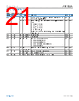
19 / 25 page  Data Sheet ADL5309 SERIAL PORT INTERFACE analog.com Rev. 0 | 19 of 25 PROTOCOL The ADL5309 can be connected to an I2C bus interface as a target device to control and monitor several internal (analog) functions. Up to three ADL5309 devices can be connected to the same I2C bus, each with its own unique device address. See Table 2 for detailed timing requirements. Data is transferred one byte at a time, with the MSB first. Each instruction consists of one address byte, followed by one or more data bytes. The ADL5309 supports single-byte read and write methods, as well as autoincrement read/write instructions. ADDRESS SELECTION The ADL5309 I2C device address can be selected from three choices by connecting the SBA pin to either ground, the positive supply, or by leaving the pin floating (see Table 1). The I2C address selected through the SBA pin can also be read from Register 0x01. The selected 7-bit device address is followed by one read/ write LSB address bit. The LSB address bit equals '0' for a write instruction and '1' for a read instruction. For example, the write address corresponding to the I2C device Address 0x6C is obtained by adding an LSB = 0, equivalent to a left-shift of one bit position (multiply-by-two), resulting in 0xD8. The bus read address equals the write address with the LSB changed from '0' to '1', which equals 0xD9. SUPPORTED READ AND WRITE METHODS The ADL5309 supports several I2C read and write methods: ► Read/write a single register ► Read/write multiple registers in a single operation through auto- increment ► Read/write a single shadow register using indirect addressing Figure 51 summarizes the procedure for each method. Each trans- action on the I2C bus is initiated by the controller and starts with sending a start condition, a high to low transition on the SDA line while SCK is high. Subsequently, the 8-bit device address (of the selected target) is transmitted, one bit per SCK clock pulse. All addresses and data are transmitted over the bus with the MSB first. The ninth clock pulse is reserved to transmit the ACK (acknowl- edge) signal from the target to the controller to indicate that the address was received. To send an ACK, the target pulls the SDA line low. A NACK (not acknowledge) results if the SDA line remains high. Depending on the transaction, a series of byte read/write transfers follow, each ending with an ACK or NACK bit. The trans- action ends with a stop condition sent by the controller and a low to high transition on the SDA line while SCK is high. The autoincrement feature provides read/write access to multiple consecutive registers in a single transaction. Each data byte is read from/written to the next register, with address one higher than the previous. The indirect addressing methods are used to access the ADL5309 shadow registers, as explained in more detail in the Shadow Ac- cess Registers section. Figure 51. ADL5309 Serial Bus Read/Write Sequences |
|
|
Link URL |
| Lei ha avuto il aiuto da alldatasheet? [ DONATE ] |
Di alldatasheet | Richest di pubblicita | contatti | Privacy Policy | Collegamento alla scheda tecnica | scambio Link | Ricerca produttore All Rights Reserved©Alldatasheet.com |
| Russian : Alldatasheetru.com | Korean : Alldatasheet.co.kr | Spanish : Alldatasheet.es | French : Alldatasheet.fr | Italian : Alldatasheetit.com Portuguese : Alldatasheetpt.com | Polish : Alldatasheet.pl | Vietnamese : Alldatasheet.vn Indian : Alldatasheet.in | Mexican : Alldatasheet.com.mx | British : Alldatasheet.co.uk | New Zealand : Alldatasheet.co.nz |
|
Family Site : ic2ic.com |
icmetro.com |
 Italian ▼
 English
 Chinese
 German
 Japanese
 Russian
 Korean
 Spanish
 French
 Italian
 Portuguese
 Polish
 Vietnamese
 Indian
 Mexican
 British
 New Zealand