|
Motore di ricerca datesheet componenti elettronici |
|
|
Motore di ricerca datesheet componenti elettronici |
|
V58C265404S Scheda tecnica(PDF) 4 Page - Mosel Vitelic, Corp |
|
|
|||||||||||||||||||||||||||||
V58C265404S Scheda tecnica(HTML) 4 Page - Mosel Vitelic, Corp |
|
|
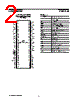
4 / 44 page  4 V58C265404S Rev. 1.4 January 2000 MOSEL VITELIC V58C265404S Signal Pin Description Pin Type Signal Polarity Function CLK CLK Input Pulse Positive Edge The system clock input. All inputs except DQs and DMs are sampled on the rising edge of CLK. CKE Input Level Active High Activates the CLK signal when high and deactivates the CLK signal when low, thereby initiates either the Power Down mode, Suspend mode, or the Self Refresh mode. CS Input Pulse Active Low CS enables the command decoder when low and disables the command decoder when high. When the command decoder is disabled, new commands are ignored but previous operations continue. RAS, CAS WE Input Pulse Active Low When sampled at the positive rising edge of the clock, CAS, RAS, and WE define the command to be executed by the SDRAM. DQS Input/ Output Pulse Active High Active on both edges for data input and output. Center aligned to input data Edge aligned to output data A0 - A11 Input Level — During a Bank Activate command cycle, A0-A11 defines the row address (RA0-RA11) when sampled at the rising clock edge. During a Read or Write command cycle, A0-An defines the column address (CA0-CAn) when sampled at the rising clock edge.CAn depends from the SDRAM organization: 8M x 8 SDRAM CAn = CA8 (Page Length = 512 bits) In addition to the column address, A10(=AP) is used to invoke autoprecharge operation at the end of the burst read or write cycle. If A10 is high, autoprecharge is selected and BA0, BA1 defines the bank to be precharged. If A10 is low, autoprecharge is disabled. During a Precharge command cycle, A10(=AP) is used in conjunction with BA0 and BA1 to control which bank(s) to precharge. If A10 is high, all four banks will be precharged simultaneously regardless of state of BA0 and BA1. BA0, BA1 Input Level — Selects which bank is to be active. DQx Input/ Output Level — Data Input/Output pins operate in the same manner as on conventional DRAMs. DM Input Pulse Active High In Write mode, DM has a latency of zero and operates as a word mask by allowing input data to be written if it is low but blocks the write operation if is high. VDD, VSS Supply Power and ground for the input buffers and the core logic. VDDQ VSSQ Supply — — Isolated power supply and ground for the output buffers to provide improved noise immunity. VREF Input Level — SSTL Reference Voltage for Inputs |
|
Link URL |
| Lei ha avuto il aiuto da alldatasheet? [ DONATE ] |
Di alldatasheet | Richest di pubblicita | contatti | Privacy Policy | Collegamento alla scheda tecnica | scambio Link | Ricerca produttore All Rights Reserved©Alldatasheet.com |
| Russian : Alldatasheetru.com | Korean : Alldatasheet.co.kr | Spanish : Alldatasheet.es | French : Alldatasheet.fr | Italian : Alldatasheetit.com Portuguese : Alldatasheetpt.com | Polish : Alldatasheet.pl | Vietnamese : Alldatasheet.vn Indian : Alldatasheet.in | Mexican : Alldatasheet.com.mx | British : Alldatasheet.co.uk | New Zealand : Alldatasheet.co.nz |
|
Family Site : ic2ic.com |
icmetro.com |
 Italian ▼
 English
 Chinese
 German
 Japanese
 Russian
 Korean
 Spanish
 French
 Italian
 Portuguese
 Polish
 Vietnamese
 Indian
 Mexican
 British
 New Zealand