|
Motore di ricerca datesheet componenti elettronici |
|
|
Motore di ricerca datesheet componenti elettronici |
|
MPC8378E Scheda tecnica(PDF) 80 Page - Freescale Semiconductor, Inc |
|
|
|||||||||||||||||||||||||||||
MPC8378E Scheda tecnica(HTML) 80 Page - Freescale Semiconductor, Inc |
|
|
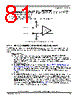
80 / 126 page  MPC8378E PowerQUICC™ II Pro Processor Hardware Specifications, Rev. 2 80 Freescale Semiconductor High-Speed Serial Interfaces (HSSI) To illustrate these definitions using real values, consider the case of a CML (Current Mode Logic) transmitter that has a common mode voltage of 2.25 V and each of its outputs, TD and TD, has a swing that goes between 2.5 V and 2.0 V. Using these values, the peak-to-peak voltage swing of each signal (TD or TD) is 500 mVp-p, which is referred as the single-ended swing for each signal. In this example, since the differential signaling environment is fully symmetrical, the transmitter output’s differential swing (VOD) has the same amplitude as each signal’s single-ended swing. The differential output signal ranges between 500 mV and –500 mV, in other words, VOD is 500 mV in one phase and –500 mV in the other phase. The peak differential voltage (VDIFFp) is 500 mV. The peak-to-peak differential voltage (VDIFFp-p) is 1000 mVp-p. 20.2 SerDes Reference Clocks The SerDes reference clock inputs are applied to an internal PLL whose output creates the clock used by the corresponding SerDes lanes. The SerDes reference clocks inputs are SD1_REF_CLK and SD1_REF_CLK for both lanes of SerDes1, and SD2_REF_CLK and SD2_REF_CLK for both lanes of SerDes2. The following sections describe the SerDes reference clock requirements and some application information. 20.2.1 SerDes Reference Clock Receiver Characteristics Figure 55 shows a receiver reference diagram of the SerDes reference clocks. • SerDes Reference Clock Receiver Reference Circuit Structure —The SDn_REF_CLK and SDn_REF_CLK are internally AC-coupled differential inputs as shown in Figure 55. Each differential clock input (SDn_REF_CLK or SDn_REF_CLK) has a 50 Ω termination to SGND_SRDSn (xcorevss) followed by on-chip AC-coupling. — The external reference clock driver must be able to drive this termination. — The SerDes reference clock input can be either differential or single-ended. Refer to the Differential Mode and Single-ended Mode description below for further detailed requirements. • The maximum average current requirement that also determines the common mode voltage range — When the SerDes reference clock differential inputs are DC coupled externally with the clock driver chip, the maximum average current allowed for each input pin is 8 mA. In this case, the exact common mode input voltage is not critical as long as it is within the range allowed by the maximum average current of 8 mA (refer to the following bullet for more detail), since the input is AC-coupled on-chip. — This current limitation sets the maximum common mode input voltage to be less than 0.4 V (0.4 V ÷ 50 = 8 mA) while the minimum common mode input level is 0.1 V above SGND_SRDSn (xcorevss). For example, a clock with a 50/50 duty cycle can be produced by a clock driver with output driven by its current source from 0 mA to 16 mA (0–0.8 V), such that each phase of the differential input has a single-ended swing from 0 V to 800 mV with the common mode voltage at 400 mV. |
|
Link URL |
| Lei ha avuto il aiuto da alldatasheet? [ DONATE ] |
Di alldatasheet | Richest di pubblicita | contatti | Privacy Policy | Collegamento alla scheda tecnica | scambio Link | Ricerca produttore All Rights Reserved©Alldatasheet.com |
| Russian : Alldatasheetru.com | Korean : Alldatasheet.co.kr | Spanish : Alldatasheet.es | French : Alldatasheet.fr | Italian : Alldatasheetit.com Portuguese : Alldatasheetpt.com | Polish : Alldatasheet.pl | Vietnamese : Alldatasheet.vn Indian : Alldatasheet.in | Mexican : Alldatasheet.com.mx | British : Alldatasheet.co.uk | New Zealand : Alldatasheet.co.nz |
|
Family Site : ic2ic.com |
icmetro.com |
 Italian ▼
 English
 Chinese
 German
 Japanese
 Russian
 Korean
 Spanish
 French
 Italian
 Portuguese
 Polish
 Vietnamese
 Indian
 Mexican
 British
 New Zealand