|
Motore di ricerca datesheet componenti elettronici |
|
|
Motore di ricerca datesheet componenti elettronici |
|
AN753 Scheda tecnica(PDF) 13 Page - Maxim Integrated Products |
|
|
|||||||||||||||||||||||||||||
AN753 Scheda tecnica(HTML) 13 Page - Maxim Integrated Products |
|
|
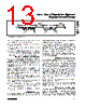
13 / 24 page  1) Write the 16 data bits to DHR[15:0] using four byte accesses into the interface register set. 2) Write the address of the target internal calibration register to ICRA[3:0]. 3) Write the load internal calibration register (LdICR) command to CRIL[3:0]. When a LdICR command is issued to the CRIL register, the calibration register loaded depends on the address in the internal calibration register address (ICRA). Table 11 specifies which calibration register is decoded. Erasing and Writing the EEPROM The internal EEPROM needs to be erased (bytes set to FFhex) prior to programming the desired contents. Remember to save the 3 MSBs of byte 161hex (high- byte of the configuration register) and restore it when programming its contents to prevent modification of the trimmed oscillator frequency. The internal EEPROM can be entirely erased with the ERASE command, or partially erased with the PageErase command (see Table 10, CRIL command). It is necessary to wait 6ms after issuing the ERASE or PageErase command. After the EEPROM bytes have been erased (value of every byte = FFhex), the user can program its contents, following the procedure below: 1) Write the 8 data bits to DHR[7:0] using two byte accesses into the interface register set. 2) Write the address of the target internal EEPROM location to IEEA[9:0] using three byte accesses into the interface register set. 3) Write the EEPROM write command (EEPW) to CRIL[3:0]. Serial Digital Output When a RdIRS command is written to CRIL[3:0], DIO is configured as a digital output and the contents of the register designated by IRSP[3:0] are sent out as a byte framed by a start bit and a stop bit. Once the tester finishes sending the RdIRS command, it must three-state its connection to DIO to allow the MAX1452 to drive the DIO line. The MAX1452 will three- state DIO high for 1 byte time and then drive with the start bit in the next bit period followed by the data byte and stop bit. The sequence is shown in Figure 5. The data returned on a RdIRS command depends on the address in IRSP. Table 12 defines what is returned for the various addresses. Multiplexed Analog Output When a RdAlg command is written to CRIL[3:0] the analog signal designated by ALOC[3:0] is asserted on the OUT pin. The duration of the analog signal is deter- mined by ATIM[3:0] after which the pin reverts to three- state. While the analog signal is asserted in the OUT pin, DIO is simultaneously three-stated, enabling a par- allel wiring of DIO and OUT. When DIO and OUT are connected in parallel, the host computer or calibration system must three-state its connection to DIO after asserting the stop bit. Do not load the OUT line when reading internal signals, such as BDR, FSOTC...etc. The analog output sequence with DIO and OUT is shown in Figure 6. The duration of the analog signal is controlled by ATIM[3:0] as given in Table 13. The analog signal driven onto the OUT pin is deter- mined by the value in the ALOC register. The signals are specified in Table 14. Test System Configuration The MAX1452 is designed to support an automated production test system with integrated calibration and temperature compensation. Figure 7 shows the imple- mentation concept for a low-cost test system capable of testing many transducer modules connected in par- Low-Cost Precision Sensor Signal Conditioner ______________________________________________________________________________________ 13 DRIVEN BY TESTER DRIVEN BY MAX1452 THREE-STATE NEED WEAK PULLUP THREE-STATE NEED WEAK PULLUP 11 1 1 1 0 1 0 0 1 1 0 1 0 1 1 111 11 1 1 10 0 0 0 0 1 0 0 0 1 11 1 1 1 1 1 1 11 DIO Figure 5. DIO Output Data Format |
|
|
Link URL |
| Lei ha avuto il aiuto da alldatasheet? [ DONATE ] |
Di alldatasheet | Richest di pubblicita | contatti | Privacy Policy | Collegamento alla scheda tecnica | scambio Link | Ricerca produttore All Rights Reserved©Alldatasheet.com |
| Russian : Alldatasheetru.com | Korean : Alldatasheet.co.kr | Spanish : Alldatasheet.es | French : Alldatasheet.fr | Italian : Alldatasheetit.com Portuguese : Alldatasheetpt.com | Polish : Alldatasheet.pl | Vietnamese : Alldatasheet.vn Indian : Alldatasheet.in | Mexican : Alldatasheet.com.mx | British : Alldatasheet.co.uk | New Zealand : Alldatasheet.co.nz |
|
Family Site : ic2ic.com |
icmetro.com |
 Italian ▼
 English
 Chinese
 German
 Japanese
 Russian
 Korean
 Spanish
 French
 Italian
 Portuguese
 Polish
 Vietnamese
 Indian
 Mexican
 British
 New Zealand