|
Motore di ricerca datesheet componenti elettronici |
|
|
Motore di ricerca datesheet componenti elettronici |
|
AN753 Scheda tecnica(PDF) 14 Page - Maxim Integrated Products |
|
|
|||||||||||||||||||||||||||||
AN753 Scheda tecnica(HTML) 14 Page - Maxim Integrated Products |
|
|
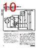
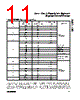
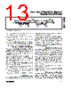
14 / 24 page  allel. The MAX1452 allows for a high degree of flexibili- ty in system calibration design. This is achieved by use of single-wire digital communication and three-state output nodes. Depending upon specific calibration requirements one may connect all the OUTs in parallel or connect DIO and OUT on each individual module. Sensor Compensation Overview Compensation requires an examination of the sensor performance over the operating pressure and tempera- ture range. Use a minimum of two test pressures (e.g., zero and full-span) and two temperatures. More test pressures and temperatures will result in greater accu- racy. A typical compensation procedure can be sum- marized as follows: Set reference temperature (e.g., 25°C): • Initialize each transducer by loading their respec- tive registers with default coefficients (e.g., based on mean values of offset, FSO and bridge resis- tance) to prevent overload of the MAX1452. • Set the initial bridge voltage (with the FSODAC) to half of the supply voltage. Measure the bridge volt- age using the BDR or OUT pins, or calculate based on measurements. • Calibrate the output offset and FSO of the transduc- er using the ODAC and FSODAC, respectively. • Store calibration data in the test computer or MAX1452 EEPROM user memory. Set next test temperature: • Calibrate offset and FSO using the ODAC and FSO- DAC, respectively. • Store calibration data in the test computer or MAX1452 EEPROM user memory. • Calculate the correction coefficients. • Download correction coefficients to EEPROM. • Perform a final test. Sensor Calibration and Compensation Example The MAX1452 temperature compensation design cor- rects both sensor and IC temperature errors. This enables the MAX1452 to provide temperature compen- sation approaching the inherent repeatability of the sensor. An example of the MAX1452’s capabilities is shown in Figure 8. A repeatable piezoresistive sensor with an initial offset of 16.4mV and a span of 55.8mV was converted into a compensated transducer (utilizing the piezoresistive sensor with the MAX1452) with an offset of 0.5000V and a span of 4.0000V. Nonlinear sensor offset and FSO temperature errors, which were on the order of 20% to 30% FSO, were reduced to under ±0.1% FSO. The fol- lowing graphs show the output of the uncompensated sensor and the output of the compensated transducer. Six temperature points were used to obtain this result. MAX1452 Evaluation Kit To expedite the development of MAX1452 based transducers and test systems, Maxim has pro- duced the MAX1452 evaluation kit (EV kit). First-time users of the MAX1452 are strongly encouraged to use this kit. Low-Cost Precision Sensor Signal Conditioner 14 ______________________________________________________________________________________ DRIVEN BY TESTER THREE-STATE NEED WEAK PULLUP THREE-STATE NEED WEAK PULLUP 11 1 1 1 0 1 0 0 1 1 0 1 0 1 1 111 11 1 1 1 1 1 1 1 1 1 11 11 1 1 11 1 11 1 11 THREE-STATE 2ATIM +1 BYTE TIMES DIO OUT VALID OUT HIGH IMPEDANCE Figure 6. Analog Output Timing |
|
|
Link URL |
| Lei ha avuto il aiuto da alldatasheet? [ DONATE ] |
Di alldatasheet | Richest di pubblicita | contatti | Privacy Policy | Collegamento alla scheda tecnica | scambio Link | Ricerca produttore All Rights Reserved©Alldatasheet.com |
| Russian : Alldatasheetru.com | Korean : Alldatasheet.co.kr | Spanish : Alldatasheet.es | French : Alldatasheet.fr | Italian : Alldatasheetit.com Portuguese : Alldatasheetpt.com | Polish : Alldatasheet.pl | Vietnamese : Alldatasheet.vn Indian : Alldatasheet.in | Mexican : Alldatasheet.com.mx | British : Alldatasheet.co.uk | New Zealand : Alldatasheet.co.nz |
|
Family Site : ic2ic.com |
icmetro.com |
 Italian ▼
 English
 Chinese
 German
 Japanese
 Russian
 Korean
 Spanish
 French
 Italian
 Portuguese
 Polish
 Vietnamese
 Indian
 Mexican
 British
 New Zealand