|
Motore di ricerca datesheet componenti elettronici |
|
|
Motore di ricerca datesheet componenti elettronici |
|
ATS684LSN Scheda tecnica(PDF) 8 Page - Allegro MicroSystems |
|
|
|||||||||||||||||||||||||||||
ATS684LSN Scheda tecnica(HTML) 8 Page - Allegro MicroSystems |
|
|
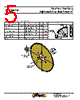
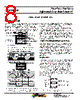
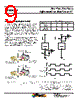
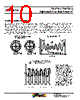
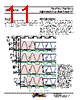
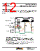
8 / 16 page  Two-Wire, Zero-Speed Differential Gear Tooth Sensor IC ATS684LSN 8 Allegro MicroSystems, LLC 115 Northeast Cutoff Worcester, Massachusetts 01615-0036 U.S.A. 1.508.853.5000; www.allegromicro.com FUNCTIONAL DESCRIPTION The ATS684 sensor IC contains a single-chip differential Hall- effect circuit, a samarium-cobalt pellet, and a flat ferrous pole piece (a precisely-mounted magnetic field concentrator that homogenizes the flux passing through the Hall chip). As shown in Figure 1, the circuit supports two Hall elements, which sense the magnetic profile of the ferromagnetic gear target simultaneously, but at different points (spaced at a 2.2 mm pitch), generating a differential internal analog voltage, VPROC, that is processed for precise switching of the digital output signal. The Hall IC is self-calibrating and also integrates a tempera- ture compensated amplifier and offset cancellation circuitry. Its voltage regulator provides supply noise rejection throughout the operating voltage range. Changes in temperature do not greatly affect this device due to the stable amplifier design and the offset rejection circuitry. The Hall transducers and signal processing electronics are integrated on the same silicon substrate, using a proprietary BiCMOS process. Target Profiling During Operation Under normal operating conditions, the IC is capable of provid- ing digital information that is representative of the mechanical features of a rotating gear. The waveform diagram in Figure 2 presents the automatic translation of the mechanical profile, through the magnetic profile that it induces, to the digital output signal of the ATS684. No additional optimization is needed and minimal processing circuitry is required. This ease of use reduces design time and incremental assembly costs for most applications. Diagnostics The regulated current output is configured for two-wire applica- tions, requiring one less wire for operation than do switches with the traditional open-collector output. Additionally, the system designer inherently gains diagnostics because there is always output current flowing, which should be in either of two nar- row ranges, shown in Figure 3 as ICC(HIGH) and ICC(LOW). Any current level not within these ranges indicates a fault condition. If ICC > ICC(HIGH)(max), then a short condition exists, and if ICC < ICC(LOW)(min), then an open condition exists. Any value of ICC between the allowed ranges for ICC(HIGH) and ICC(LOW) indicates a general fault condition. Target (Gear) Hall Element 2 Dual-Element Hall Effect Device South Pole North Pole (Pin > 1 Side) n (Pin 1 Side) Case Back-biasing Magnet Pole Piece (Concentrator Hall IC Hall Element 1 Element Pitch Figure 1: Relative Motion of the Target is Detected by the Dual Hall Elements Mounted on the Hall IC. Figure 2: The Magnetic Prof ile Ref lects the Geometry of the Target, Allowing the ATS684 to Present an Ac- curate Digital Output Response. BRP(#1) BRP(#2) BOP(#2) On Off Off On Sensor Internal Switch State Sensor Orientation to Target Sensor Internal Differential Analog Signal, VPROC Mechanical Position (Target moves past pin 1 to pin 3) Sensor Output Signal, IOUT Target (Gear) (Package Top View) Sensor Branded Face Pin 1 Side Pin 3 Side Branded Face Hall Element Pitch Target Magnetic Profile +B This tooth sensed earlier This tooth sensed later Back-Biasing Pellet IC +t ICC(HIGH)(max) ICC(HIGH)(min) ICC(LOW)(max) ICC(LOW)(min) Range for Valid ICC(HIGH) Range for Valid ICC(LOW) 0 +mA Short Fault Open Figure 3: Diagnostic Characteristics of Supply Current Values. Sensing Technology |
|
|
Link URL |
| Lei ha avuto il aiuto da alldatasheet? [ DONATE ] |
Di alldatasheet | Richest di pubblicita | contatti | Privacy Policy | Collegamento alla scheda tecnica | scambio Link | Ricerca produttore All Rights Reserved©Alldatasheet.com |
| Russian : Alldatasheetru.com | Korean : Alldatasheet.co.kr | Spanish : Alldatasheet.es | French : Alldatasheet.fr | Italian : Alldatasheetit.com Portuguese : Alldatasheetpt.com | Polish : Alldatasheet.pl | Vietnamese : Alldatasheet.vn Indian : Alldatasheet.in | Mexican : Alldatasheet.com.mx | British : Alldatasheet.co.uk | New Zealand : Alldatasheet.co.nz |
|
Family Site : ic2ic.com |
icmetro.com |
 Italian ▼
 English
 Chinese
 German
 Japanese
 Russian
 Korean
 Spanish
 French
 Italian
 Portuguese
 Polish
 Vietnamese
 Indian
 Mexican
 British
 New Zealand