|
Motore di ricerca datesheet componenti elettronici |
|
|
Motore di ricerca datesheet componenti elettronici |
|
ATS684LSN Scheda tecnica(PDF) 9 Page - Allegro MicroSystems |
|
|
|||||||||||||||||||||||||||||
ATS684LSN Scheda tecnica(HTML) 9 Page - Allegro MicroSystems |
|
|
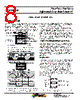
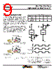
9 / 16 page  Two-Wire, Zero-Speed Differential Gear Tooth Sensor IC ATS684LSN 9 Allegro MicroSystems, LLC 115 Northeast Cutoff Worcester, Massachusetts 01615-0036 U.S.A. 1.508.853.5000; www.allegromicro.com Determining Output Signal Polarity In Figure 2, the top panel, labeled Mechanical Position, repre- sents the mechanical features of the target gear and orientation to the device. The bottom panel, labeled Device Output Signal, displays the square waveform corresponding to the digital output signal (current amplitude) that results from a rotating gear config- ured as shown in Figure 4. Referring to the target side nearest the face of the sensor IC, the direction of rotation is: perpendicular to the leads, across the face of the device, from the pin 1 side to the pin 3 side. To read the output signal as a voltage (VSENSE), a sense resistor (RSENSE) can be placed on either the VCC signal or on the GND signal. As shown in Figure 5, when RSENSE is placed on the GND signal, the output signal voltage (VSENSE(LowSide)) is in phase with ICC. When RSENSE is placed on the VCC signal, the output signal voltage (VSENSE(HighSide)) is inverted relative to ICC. Figure 4: Left-to-Right, Pin 1 to Pin 3 (top) and Right-to- Left, Pin 3 to Pin 1 (bottom) Direction of Target Rotation. Figure 5: Alternative Polarity Conf igurations Using Two-Wire Sensing. The Output Polarity States table provides the permutations of output voltage relative to ICC, given alternative locations for RSENSE. Panel A shows the low-side (VSENSE(LowSide)) sensing configuration, and panel B shows the high-side (VSENSE(HighSide)) configuration. As shown in panel C, VSENSE(LowSide) is in phase with ICC, and VSENSE(HighSide), is inverted. V DD V DD I CC I CC 11 VCC VCC ATS684 ATS684 GND GND 33 R LOAD 100 W R LOAD 100 W C LOAD C LOAD Output Polarity States RSENSE Location ICC State VSENSE State High side (VCC pin side) High Low Low High Low side (GND pin side) High High Low Low I+ V+ V+ I CC V SENSE(LowSide) V SENSE(HighSide) Panel A Panel B Panel C |
|
|
Link URL |
| Lei ha avuto il aiuto da alldatasheet? [ DONATE ] |
Di alldatasheet | Richest di pubblicita | contatti | Privacy Policy | Collegamento alla scheda tecnica | scambio Link | Ricerca produttore All Rights Reserved©Alldatasheet.com |
| Russian : Alldatasheetru.com | Korean : Alldatasheet.co.kr | Spanish : Alldatasheet.es | French : Alldatasheet.fr | Italian : Alldatasheetit.com Portuguese : Alldatasheetpt.com | Polish : Alldatasheet.pl | Vietnamese : Alldatasheet.vn Indian : Alldatasheet.in | Mexican : Alldatasheet.com.mx | British : Alldatasheet.co.uk | New Zealand : Alldatasheet.co.nz |
|
Family Site : ic2ic.com |
icmetro.com |
 Italian ▼
 English
 Chinese
 German
 Japanese
 Russian
 Korean
 Spanish
 French
 Italian
 Portuguese
 Polish
 Vietnamese
 Indian
 Mexican
 British
 New Zealand