|
Motore di ricerca datesheet componenti elettronici |
|
|
Motore di ricerca datesheet componenti elettronici |
|
ATS684LSN Scheda tecnica(PDF) 12 Page - Allegro MicroSystems |
|
|
|||||||||||||||||||||||||||||
ATS684LSN Scheda tecnica(HTML) 12 Page - Allegro MicroSystems |
|
|
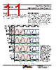
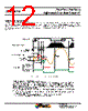
12 / 16 page  Two-Wire, Zero-Speed Differential Gear Tooth Sensor IC ATS684LSN 12 Allegro MicroSystems, LLC 115 Northeast Cutoff Worcester, Massachusetts 01615-0036 U.S.A. 1.508.853.5000; www.allegromicro.com This feature helps to ensure optimal self-calibration by rejecting electrical noise and low-amplitude target vibration during initial- ization. This prevents AGC from calibrating the device on such spurious signals. Calibration can be performed using the actual target features. A typical scenario is shown in Figure 8. The hysteresis (POHYS) is a minimum level of the peak-to-peak amplitude of the internal analog electrical signal (VPROC) that must be exceeded before the ATS684 starts to compute switchpoints. BOP BRP BRP BRP(initial) BOP(initial) 1 4 2 3 Start Mode Output Signal, ICC If exceed PO HYS on high side If exceed PO HYS on low side IC Position Relative to Target Target Magnetic Profile Differential Signal, VPROC Target, Gear Hysteresis, POHYS Figure 8: Operation of Start Mode Hysteresis • At power-on (position 1), the ATS684 begins sampling VPROC. • At the point where the Start Mode Hysteresis, POHYS, is exceeded, the device establishes an initial switching threshold, by using the Continuous Update algorithm. If VPROC is rising through the limit on the high side (position 2), the switchpoint is BOP, and if VPROC is falling through the limit on the low side (position 4), it is BRP. After this point, Start Mode Hysteresis is no longer a consideration. Note that a valid VPROC value exceeding the Start Mode Hysteresis can be generated either by a legitimate target feature or by excessive vibration. • In either case (BOP or BRP), because the switchpoint is immediately passed as soon as it is established, the ATS684 enables switching: ▫ If on the high side, at BOP (position 2) the output would switch from low to high. However, because output is already high, no output switching occurs. At the next switchpoint, where BRP is passed (position 3), the output switches from high to low. ▫ If on the low side, at BRP (position 4) the output switches from high to low. Start Mode Hysteresis |
|
|
Link URL |
| Lei ha avuto il aiuto da alldatasheet? [ DONATE ] |
Di alldatasheet | Richest di pubblicita | contatti | Privacy Policy | Collegamento alla scheda tecnica | scambio Link | Ricerca produttore All Rights Reserved©Alldatasheet.com |
| Russian : Alldatasheetru.com | Korean : Alldatasheet.co.kr | Spanish : Alldatasheet.es | French : Alldatasheet.fr | Italian : Alldatasheetit.com Portuguese : Alldatasheetpt.com | Polish : Alldatasheet.pl | Vietnamese : Alldatasheet.vn Indian : Alldatasheet.in | Mexican : Alldatasheet.com.mx | British : Alldatasheet.co.uk | New Zealand : Alldatasheet.co.nz |
|
Family Site : ic2ic.com |
icmetro.com |
 Italian ▼
 English
 Chinese
 German
 Japanese
 Russian
 Korean
 Spanish
 French
 Italian
 Portuguese
 Polish
 Vietnamese
 Indian
 Mexican
 British
 New Zealand