|
Motore di ricerca datesheet componenti elettronici |
|
|
Motore di ricerca datesheet componenti elettronici |
|
MCP3202 Scheda tecnica(PDF) 16 Page - Microchip Technology |
|
|
|||||||||||||||||||||||||||||
MCP3202 Scheda tecnica(HTML) 16 Page - Microchip Technology |
|
|
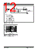
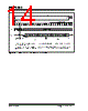
16 / 28 page  MCP3202 DS21034D-page 16 © 2006 Microchip Technology Inc. 6.2 Maintaining Minimum Clock Speed When the MCP3202 initiates the sample period, charge is stored on the sample capacitor. When the sample period is complete, the device converts one bit for each clock that is received. It is important for the user to note that a slow clock rate will allow charge to bleed off the sample cap while the conversion is taking place. At 85°C (worst case condition), the part will maintain proper charge on the sample capacitor for at least 1.2 ms after the sample period has ended. This means that the time between the end of the sample period and the time that all 12 data bits have been clocked out must not exceed 1.2 ms (effective clock frequency of 10 kHz). Failure to meet this criteria may induce linear- ity errors into the conversion outside the rated specifi- cations. It should be noted that during the entire conversion cycle, the A/D Converter does not require a constant clock speed or duty cycle, as long as all timing specifications are met. 6.3 Buffering/Filtering the Analog Inputs If the signal source for the A/D Converter is not a low impedance source, it will have to be buffered or inaccu- rate conversion results may occur. It is also recom- mended that a filter be used to eliminate any signals that may be aliased back into the conversion results. This is illustrated in Figure 6-3 below where an op amp is used to drive the analog input of the MCP3202. This amplifier provides a low impedance output for the con- verter input and a low pass filter, which eliminates unwanted high frequency noise. Low pass (anti-aliasing) filters can be designed using Microchip’s interactive FilterLab™ software. FilterLab will calculate capacitor and resistor values, as well as, determine the number of poles that are required for the application. For more information on filtering signals, see the application note AN699 “Anti-Aliasing Analog Filters for Data Acquisition Systems. ” FIGURE 6-3: The MCP601 Operational Amplifier is used to implement a 2nd order anti-aliasing filter for the signal being converted by the MCP3202. 6.4 Layout Considerations When laying out a printed circuit board for use with analog components, care should be taken to reduce noise wherever possible. A bypass capacitor should always be used with this device and should be placed as close as possible to the device pin. A bypass capac- itor value of 0.1 µF is recommended. Digital and analog traces should be separated as much as possible on the board and no traces should run underneath the device or the bypass capacitor. Extra precautions should be taken to keep traces with high frequency signals (such as clock lines) as far as possi- ble from analog traces. Use of an analog ground plane is recommended in order to keep the ground potential the same for all devices on the board. Providing VDD connections to devices in a “star” configuration can also reduce noise by eliminating current return paths and associated errors. See Figure 6-4. For more information on layout tips when using A/D Converters, refer to AN688 “Lay- out Tips for 12-Bit A/D Converter Applications” (DS00688). FIGURE 6-4: V DD traces arranged in a ‘Star’ configuration in order to reduce errors caused by current return paths. MCP3202 V DD 10 μF IN- IN+ - + V IN C1 C2 0.1 μF MCP601 R1 R2 R3 R4 VDD Connection Device 1 Device 2 Device 3 Device 4 |
|
Link URL |
| Lei ha avuto il aiuto da alldatasheet? [ DONATE ] |
Di alldatasheet | Richest di pubblicita | contatti | Privacy Policy | Collegamento alla scheda tecnica | scambio Link | Ricerca produttore All Rights Reserved©Alldatasheet.com |
| Russian : Alldatasheetru.com | Korean : Alldatasheet.co.kr | Spanish : Alldatasheet.es | French : Alldatasheet.fr | Italian : Alldatasheetit.com Portuguese : Alldatasheetpt.com | Polish : Alldatasheet.pl | Vietnamese : Alldatasheet.vn Indian : Alldatasheet.in | Mexican : Alldatasheet.com.mx | British : Alldatasheet.co.uk | New Zealand : Alldatasheet.co.nz |
|
Family Site : ic2ic.com |
icmetro.com |
 Italian ▼
 English
 Chinese
 German
 Japanese
 Russian
 Korean
 Spanish
 French
 Italian
 Portuguese
 Polish
 Vietnamese
 Indian
 Mexican
 British
 New Zealand