|
Motore di ricerca datesheet componenti elettronici |
|
|
Motore di ricerca datesheet componenti elettronici |
|
MIC2174 Scheda tecnica(PDF) 11 Page - Micrel Semiconductor |
|
|
|||||||||||||||||||||||||||||
MIC2174 Scheda tecnica(HTML) 11 Page - Micrel Semiconductor |
|
|
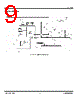
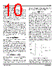
11 / 24 page  Micrel, Inc. MIC2174 September 2009 11 M9999-090409-B comparator to trigger ON-time period. At the end of the ON-time period, a minimum OFF time TOFF(min) is generated to charge BST since the FB voltage is still below the VREF. Then, the next ON-time period is triggered due to the low FB voltage. Therefore, the switching frequency changes during the load transient. With the varying duty cycle and switching frequency, the output recovery time is fast and the output voltage deviation is small in MIC2174 converter. Figure 3. MIC2174 Load-Transient Response Unlike the current-mode control, MIC2174 uses the output voltage ripple, which is proportional to the inductor current ripple if the ESR of the output capacitor is large enough, to trigger an ON-time period. The predetermined ON time makes MIC2174 control loop has the advantage as the adaptive on-time mode control. Therefore, the slope compensation, which is necessary for the current-mode control, is not required in the MIC2174. The MIC2174 has its own stability concern: the FB voltage ripple should be in phase with the inductor current ripple and large enough to be sensed by the gm amplifier and the error comparator. The recommended minimum FB voltage ripple is 20mV. If a low ESR output capacitor is selected, the FB voltage ripple may be too small to be sensed by the gm amplifier and the error comparator. Also, the output voltage ripple and the FB voltage ripple are not in phase with the inductor current ripple if the ESR of the output capacitor is very low. Therefore, the ripple injection is required for a low ESR output capacitor. Please refer to “Ripple Injection” subsection in “Application Information” for more details about the ripple injection. Soft-Start Soft-start reduces the power supply input surge current at startup by controlling the output voltage rise time. The input surge appears while the output capacitor is charged up. A slower output rise time will draw a lower input surge current. MIC2174 implements an internal digital soft-start by making the 0.8V reference voltage VREF ramp from 0 to 100% in about 6ms with a 9.7mV step. Therefore, the output voltage is controlled to increase slowly by a stair- case VREF ramp. Once the soft-start ends, the related circuitry is disabled to reduce the current consumption. VIN should be powered up no earlier than VHSD to make the soft-start function behavior correctly. Current Limit The MIC2174 uses the RDS(ON) of the low-side power MOSFET to sense over-current conditions. The lower- side MOSFET is used because it displays much lower parasitic oscillations during switching then the high-side MOSFET. Using the low-side MOSFET RDS(ON) as a current sense is an excellent method for circuit protection. This method will avoid adding cost, board space and power losses taken by discrete current sense resistors. In each switching cycle of the MIC2174 converter, the inductor current is sensed by monitoring the low-side MOSFET in the OFF period. The sensed voltage is compared with a current-limit threshold voltage VCL after a blanking time of 150ns. If the sensed voltage is over VCL, which is 130mV typical at 0.8V feedback voltage, the MIC2174 turns off the high-side MOSFET and a soft- start sequence is trigged. This mode of operation is called the “hiccup mode” and its purpose is to protect the down stream load in case of a hard short. The current limit threshold VCL has a fold back characteristics related to the FB voltage. Please refer to the “Typical Characteristics” for the curve of VCL vs. FB voltage. The circuit in Figure 4 illustrates the MIC2174 current limiting circuit. Figure 4. MIC2174 Current Limiting Circuit Using the typical VCL value of 130mV, the current limit value is roughly estimated as: DS(ON) CL R 130mV I ≈ For designs where the current ripple is significant compared to the load current IOUT, or for low duty cycle operation, calculating the current limit ICL should take into account that one is sensing the peak inductor |
|
|
Link URL |
| Lei ha avuto il aiuto da alldatasheet? [ DONATE ] |
Di alldatasheet | Richest di pubblicita | contatti | Privacy Policy | Collegamento alla scheda tecnica | scambio Link | Ricerca produttore All Rights Reserved©Alldatasheet.com |
| Russian : Alldatasheetru.com | Korean : Alldatasheet.co.kr | Spanish : Alldatasheet.es | French : Alldatasheet.fr | Italian : Alldatasheetit.com Portuguese : Alldatasheetpt.com | Polish : Alldatasheet.pl | Vietnamese : Alldatasheet.vn Indian : Alldatasheet.in | Mexican : Alldatasheet.com.mx | British : Alldatasheet.co.uk | New Zealand : Alldatasheet.co.nz |
|
Family Site : ic2ic.com |
icmetro.com |
 Italian ▼
 English
 Chinese
 German
 Japanese
 Russian
 Korean
 Spanish
 French
 Italian
 Portuguese
 Polish
 Vietnamese
 Indian
 Mexican
 British
 New Zealand