|
Motore di ricerca datesheet componenti elettronici |
|
|
Motore di ricerca datesheet componenti elettronici |
|
MIC2174 Scheda tecnica(PDF) 13 Page - Micrel Semiconductor |
|
|
|||||||||||||||||||||||||||||
MIC2174 Scheda tecnica(HTML) 13 Page - Micrel Semiconductor |
|
|
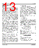
13 / 24 page  Micrel, Inc. MIC2174 September 2009 13 M9999-090409-B Application Information MOSFET Selection The MIC2174 controller works from power stage input voltages of 3V to 40V and has an external 3V to 5.5V VIN to provide power to turn the external N-Channel power MOSFETs for the high- and low-side switches. For applications where VIN < 5V, it is necessary that the power MOSFETs used are sub-logic level and are in full conduction mode for VGS of 2.5V. For applications when VIN > 5V; logic-level MOSFETs, whose operation is specified at VGS = 4.5V must be used. There are different criteria for choosing the high-side and low-side MOSFETs. These differences are more significant at lower duty cycles such as a 12V to 1.8V conversion. In such an application, the high-side MOSFET is required to switch as quickly as possible to minimize transition losses, whereas the low-side MOSFET can switch slower, but must handle larger RMS currents. When the duty cycle approaches 50%, the current carrying capability of the high-side MOSFET starts to become critical. It is important to note that the on-resistance of a MOSFET increases with increasing temperature. A 75°C rise in junction temperature will increase the channel resistance of the MOSFET by 50% to 75% of the resistance specified at 25°C. This change in resistance must be accounted for when calculating MOSFET power dissipation and in calculating the value of current limit. Total gate charge is the charge required to turn the MOSFET on and off under specified operating conditions (VDS and VGS). The gate charge is supplied by the MIC2174 gate-drive circuit. At 300kHz switching frequency and above, the gate charge can be a significant source of power dissipation in the MIC2174. At low output load, this power dissipation is noticeable as a reduction in efficiency. The average current required to drive the high-side MOSFET is: SW G side] - G[high f Q (avg) I × = (5) where: IG[high-side](avg) = Average high-side MOSFET gate current QG = Total gate charge for the high-side MOSFET taken from the manufacturer’s data sheet for VGS = VIN. fSW = Switching Frequency (300kHz) The low-side MOSFET is turned on and off at VDS = 0 because an internal body diode or external freewheeling diode is conducting during this time. The switching loss for the low-side MOSFET is usually negligible. Also, the gate-drive current for the low-side MOSFET is more accurately calculated using CISS at VDS = 0 instead of gate charge. For the low-side MOSFET: SW GS ISS side] - G[low f V C (avg) I × × = (6) Since the current from the gate drive comes from the VIN, the power dissipated in the MIC2174 due to gate drive is: (avg)) I (avg) (I V P side] - G[low side] - G[high IN GATEDRIVE + × = (7) A convenient figure of merit for switching MOSFETs is the on resistance times the total gate charge RDS(ON) × QG. Lower numbers translate into higher efficiency. Low gate-charge logic-level MOSFETs are a good choice for use with the MIC2174. Also, the RDS(ON) of the low-side MOSFET will determine the current limit value. Please refer to “Current Limit” subsection in “Functional Description” for more details. Parameters that are important to MOSFET switch selection are: • Voltage rating • On-resistance • Total gate charge The voltage ratings for the high-side and low-side MOSFETs are essentially equal to the power stage input voltage VHSD. A safety factor of 20% should be added to the VDS(max) of the MOSFETs to account for voltage spikes due to circuit parasitic elements. The power dissipated in the MOSFETs is the sum of the conduction losses during the on-time (PCONDUCTION) and the switching losses during the period of time when the MOSFETs turn on and off (PAC). AC CONDUCTION SW P P P + = (8) DS(ON) 2 SW(RMS) CONDUCTION R I P × = (9) AC(on) ) AC(off AC P P P + = (10) where: RDS(ON) = on-resistance of the MOSFET switch D = Duty Cycle = VOUT / VHSD Making the assumption that the turn-on and turn-off transition times are equal; the transition times can be approximated by: G HSD OSS IN ISS T I V C V C t × + × = (11) where: CISS and COSS are measured at VDS = 0 IG = gate-drive current The total high-side MOSFET switching loss is: SW T PK D HSD AC f t I ) V (V P × × × + = (12) |
|
|
Link URL |
| Lei ha avuto il aiuto da alldatasheet? [ DONATE ] |
Di alldatasheet | Richest di pubblicita | contatti | Privacy Policy | Collegamento alla scheda tecnica | scambio Link | Ricerca produttore All Rights Reserved©Alldatasheet.com |
| Russian : Alldatasheetru.com | Korean : Alldatasheet.co.kr | Spanish : Alldatasheet.es | French : Alldatasheet.fr | Italian : Alldatasheetit.com Portuguese : Alldatasheetpt.com | Polish : Alldatasheet.pl | Vietnamese : Alldatasheet.vn Indian : Alldatasheet.in | Mexican : Alldatasheet.com.mx | British : Alldatasheet.co.uk | New Zealand : Alldatasheet.co.nz |
|
Family Site : ic2ic.com |
icmetro.com |
 Italian ▼
 English
 Chinese
 German
 Japanese
 Russian
 Korean
 Spanish
 French
 Italian
 Portuguese
 Polish
 Vietnamese
 Indian
 Mexican
 British
 New Zealand