|
Motore di ricerca datesheet componenti elettronici |
|
|
Motore di ricerca datesheet componenti elettronici |
|
MIC2174 Scheda tecnica(PDF) 15 Page - Micrel Semiconductor |
|
|
|||||||||||||||||||||||||||||
MIC2174 Scheda tecnica(HTML) 15 Page - Micrel Semiconductor |
|
|
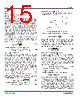
15 / 24 page  Micrel, Inc. MIC2174 September 2009 15 M9999-090409-B where: D = duty cycle COUT = output capacitance value fSW = switching frequency As described in the “Theory of Operation” subsection in “Functional Description”, the MIC2174 requires at least 20mV peak-to-peak ripple at the FB pin to make the gm amplifier and the error comparator to behavior properly. Also, the output voltage ripple should be in phase with the inductor current. Therefore the output voltage ripple caused by the output capacitor COUT should be much smaller than the ripple caused by the output capacitor ESR. If low ESR capacitors are selected as the output capacitors, such as ceramic capacitors, a ripple injection method is applied to provide the enough FB voltage ripples. Please refer to the “Ripple Injection” subsection for more details. The voltage rating of the capacitor should be twice the output voltage for a tantalum and 20% greater for aluminum electrolytic or OS-CON. The output capacitor RMS current is calculated below: 12 ΔI I L(PP) (RMS) COUT = (21) The power dissipated in the output capacitor is: OUT OUT OUT C 2 (RMS) C ) DISS(C ESR I P × = (22) Input Capacitor Selection The input capacitor for the power stage input VHSD should be selected for ripple current rating and voltage rating. Tantalum input capacitors may fail when subjected to high inrush currents, caused by turning the input supply on. A tantalum input capacitor’s voltage rating should be at least two times the maximum input voltage to maximize reliability. Aluminum electrolytic, OS-CON, and multilayer polymer film capacitors can handle the higher inrush currents without voltage de- rating. The input voltage ripple will primarily depend on the input capacitor’s ESR. The peak input current is equal to the peak inductor current, so: ΔVIN = IL(pk) × ESRCIN (23) The input capacitor must be rated for the input current ripple. The RMS value of input capacitor current is determined at the maximum output current. Assuming the peak-to-peak inductor current ripple is low: D) (1 D I I OUT(max) CIN(RMS) − × × ≈ (24) The power dissipated in the input capacitor is: PDISS(CIN) = ICIN(RMS) 2 × ESR CIN (25) Voltage Setting Components The MIC2174 requires two resistors to set the output voltage as shown in Figure 5. Figure 5. Voltage-Divider Configuration The output voltage is determined by the equation: ) R2 R1 (1 V V REF OUT + × = (26) where, VREF = 0.8V. A typical value of R1 can be between 3kΩ and 10kΩ. If R1 is too large, it may allow noise to be introduced into the voltage feedback loop. If R1 is too small in value, it will decrease the efficiency of the power supply, especially at light loads. Once R1 is selected, R2 can be calculated using: REF OUT REF V V R1 V R2 − × = (27) External Schottky Diode (Optional) An external freewheeling diode, which is not necessary, is used to keep the inductor current flow continuous while both MOSFETs are turned off. This dead time prevents current from flowing unimpeded through both MOSFETs and is typically 30ns. The diode conducts twice during each switching cycle. Although the average current through this diode is small, the diode must be able to handle the peak current. SW OUT D(avg) f 30ns 2 I I × × × = (28) The reverse voltage requirement of the diode is: HSD DIODE(rrm) V V = The power dissipated by the Schottky diode is: F D(avg) DIODE V I P × = (29) where, VF = forward voltage at the peak diode current. The external Schottky diode is not necessary for the circuit operation since the low-side MOSFET contains a parasitic body diode. The external diode will improve efficiency and decrease the high frequency noise. If the MOSFET body diode is used, it must be rated to handle the peak and average current. The body diode has a relatively slow reverse recovery time and a relatively high forward voltage drop. The power lost in the diode is |
|
|
Link URL |
| Lei ha avuto il aiuto da alldatasheet? [ DONATE ] |
Di alldatasheet | Richest di pubblicita | contatti | Privacy Policy | Collegamento alla scheda tecnica | scambio Link | Ricerca produttore All Rights Reserved©Alldatasheet.com |
| Russian : Alldatasheetru.com | Korean : Alldatasheet.co.kr | Spanish : Alldatasheet.es | French : Alldatasheet.fr | Italian : Alldatasheetit.com Portuguese : Alldatasheetpt.com | Polish : Alldatasheet.pl | Vietnamese : Alldatasheet.vn Indian : Alldatasheet.in | Mexican : Alldatasheet.com.mx | British : Alldatasheet.co.uk | New Zealand : Alldatasheet.co.nz |
|
Family Site : ic2ic.com |
icmetro.com |
 Italian ▼
 English
 Chinese
 German
 Japanese
 Russian
 Korean
 Spanish
 French
 Italian
 Portuguese
 Polish
 Vietnamese
 Indian
 Mexican
 British
 New Zealand