|
Motore di ricerca datesheet componenti elettronici |
|
|
Motore di ricerca datesheet componenti elettronici |
|
MPC8378E Scheda tecnica(PDF) 121 Page - Freescale Semiconductor, Inc |
|
|
|||||||||||||||||||||||||||||
MPC8378E Scheda tecnica(HTML) 121 Page - Freescale Semiconductor, Inc |
|
|
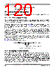
121 / 127 page  MPC8378E PowerQUICC II Pro Processor Hardware Specifications, Rev. 4 Freescale Semiconductor 121 System Design Information These capacitors should have a value of 0.01 or 0.1 µF. Only ceramic SMT (surface mount technology) capacitors should be used to minimize lead inductance, preferably 0402 or 0603 sizes. In addition, it is recommended that there be several bulk storage capacitors distributed around the PCB, feeding the VDD, OVDD, GVDD, and LVDD planes, to enable quick recharging of the smaller chip capacitors. These bulk capacitors should have a low ESR (equivalent series resistance) rating to ensure the quick response time necessary. They should also be connected to the power and ground planes through two vias to minimize inductance. Suggested bulk capacitors—100–330 µF (AVX TPS tantalum or Sanyo OSCON). 24.3 Connection Recommendations To ensure reliable operation, it is highly recommended that unused inputs be connected to an appropriate signal level. Unused active low inputs should be tied to OVDD, GVDD, or LVDD as required. Unused active high inputs should be connected to GND. All NC (no-connect) signals must remain unconnected. Power and ground connections must be made to all external VDD, GVDD, LVDD, OVDD, and GND pins of the device. 24.4 Output Buffer DC Impedance The device drivers are characterized over process, voltage, and temperature. For all buses, the driver is a push-pull single-ended driver type (open drain for I2C). To measure Z0 for the single-ended drivers, an external resistor is connected from the chip pad to OVDD or GND. Then, the value of each resistor is varied until the pad voltage is OVDD/2 (see Figure 69). The output impedance is the average of two components, the resistances of the pull-up and pull-down devices. When data is held high, SW1 is closed (SW2 is open) and RP is trimmed until the voltage at the pad equals OVDD/2. RP then becomes the resistance of the pull-up devices. RP and RN are designed to be close to each other in value. Then, Z0 = (RP + RN)/2. Figure 69. Driver Impedance Measurement OVDD OGND RP RN Pad Data SW1 SW2 |
|
Link URL |
| Lei ha avuto il aiuto da alldatasheet? [ DONATE ] |
Di alldatasheet | Richest di pubblicita | contatti | Privacy Policy | Collegamento alla scheda tecnica | scambio Link | Ricerca produttore All Rights Reserved©Alldatasheet.com |
| Russian : Alldatasheetru.com | Korean : Alldatasheet.co.kr | Spanish : Alldatasheet.es | French : Alldatasheet.fr | Italian : Alldatasheetit.com Portuguese : Alldatasheetpt.com | Polish : Alldatasheet.pl | Vietnamese : Alldatasheet.vn Indian : Alldatasheet.in | Mexican : Alldatasheet.com.mx | British : Alldatasheet.co.uk | New Zealand : Alldatasheet.co.nz |
|
Family Site : ic2ic.com |
icmetro.com |
 Italian ▼
 English
 Chinese
 German
 Japanese
 Russian
 Korean
 Spanish
 French
 Italian
 Portuguese
 Polish
 Vietnamese
 Indian
 Mexican
 British
 New Zealand