|
Motore di ricerca datesheet componenti elettronici |
|
|
Motore di ricerca datesheet componenti elettronici |
|
MAX7300AGL Scheda tecnica(PDF) 9 Page - Maxim Integrated Products |
|
|
|||||||||||||||||||||||||||||
MAX7300AGL Scheda tecnica(HTML) 9 Page - Maxim Integrated Products |
|
|
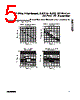
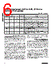
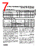
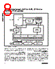
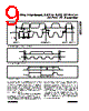
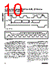
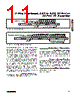
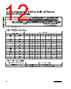
9 / 22 page  2-Wire-Interfaced, 2.5V to 5.5V, 20-Port or 28-Port I/O Expander __________________________________________________________________________ Any bytes received after the command byte are consid- ered data bytes. The first data byte goes into the inter- nal register of the MAX7300 selected by the command byte (Figure 8). If multiple data bytes are transmitted before a STOP condition is detected, these bytes are generally stored in subsequent MAX7300 internal regis- ters because the command byte address generally autoincrements (Table 4). Message Format for Reading The MAX7300 is read using the MAX7300’s internally stored command byte as address pointer, the same way the stored command byte is used as address pointer for a write. The pointer generally autoincrements after each data byte is read using the same rules as for a write (Table 4). Thus, a read is initiated by first configuring the MAX7300’s command byte by performing a write (Figure 7). The master can now read ‘n’ consecutive bytes from the MAX7300, with the first data byte being read from the register addressed by the initialized command byte (Figure 9). When performing read-after-write verification, remember to reset the command byte’s address because the stored control byte address generally has been autoincremented after the write (Table 4). Table 5 is the register address map. Figure 2. 2-Wire Serial Interface Timing Details SCL SDA START CONDITION STOP CONDITION REPEATED START CONDITION START CONDITION tSU, DAT tHD, DAT tLOW tHD, STA tHIGH tR tF tSU, STA tHD, STA tSU, STO tBUF Figure 3. Start and Stop Conditions SDA SCL S START CONDITION P STOP CONDITION SDA SCL DATA LINE STABLE; DATA VALID CHANGE OF DATA ALLOWED Figure 4. Bit Transfer |
|
|
Link URL |
| Lei ha avuto il aiuto da alldatasheet? [ DONATE ] |
Di alldatasheet | Richest di pubblicita | contatti | Privacy Policy | Collegamento alla scheda tecnica | scambio Link | Ricerca produttore All Rights Reserved©Alldatasheet.com |
| Russian : Alldatasheetru.com | Korean : Alldatasheet.co.kr | Spanish : Alldatasheet.es | French : Alldatasheet.fr | Italian : Alldatasheetit.com Portuguese : Alldatasheetpt.com | Polish : Alldatasheet.pl | Vietnamese : Alldatasheet.vn Indian : Alldatasheet.in | Mexican : Alldatasheet.com.mx | British : Alldatasheet.co.uk | New Zealand : Alldatasheet.co.nz |
|
Family Site : ic2ic.com |
icmetro.com |
 Italian ▼
 English
 Chinese
 German
 Japanese
 Russian
 Korean
 Spanish
 French
 Italian
 Portuguese
 Polish
 Vietnamese
 Indian
 Mexican
 British
 New Zealand