|
Motore di ricerca datesheet componenti elettronici |
|
|
Motore di ricerca datesheet componenti elettronici |
|
MAX7300AGL Scheda tecnica(PDF) 10 Page - Maxim Integrated Products |
|
|
|||||||||||||||||||||||||||||
MAX7300AGL Scheda tecnica(HTML) 10 Page - Maxim Integrated Products |
|
|
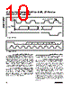
10 / 22 page  2-Wire-Interfaced, 2.5V to 5.5V, 20-Port or 28-Port I/O Expander 10 ______________________________________________________________________________________ Operation with Multiple Masters If the MAX7300 is operated on a 2-wire interface with multiple masters, a master reading the MAX7300 should use a repeated start between the write, which sets the MAX7300’s address pointer, and the read(s) that takes the data from the location(s). This is because it is possi- ble for master 2 to take over the bus after master 1 has set up the MAX7300’s address pointer, but before master 1 has read the data. If master 2 subsequently changes, the MAX7300’s address pointer, then master 1’s delayed read can be from an unexpected location. Command Address Autoincrementing Address autoincrementing allows the MAX7300 to be configured with the shortest number of transmissions by minimizing the number of times the command address needs to be sent. The command address stored in the MAX7300 generally increments after each data byte is written or read (Table 4). Initial Power-Up On initial power-up, all control registers are reset and the MAX7300 enters shutdown mode (Table 6). Transition (Port Data Change) Detection Port transition detection allows seven maskable ports P24 to P30 to be continuously monitored for changes in their logic status (Figure 10). Enable transition detec- tion by setting the M bit in the configuration register (Table 9) after setting the mask register. If port 31 is configured as an output (Tables 1 and 2), then P31 automatically becomes an interrupt request (IRQ) out- put to flag detected transitions. Port 31 can be config- ured and used as a general-purpose input port instead, if not required for use as the IRQ output. The mask register determines which of the seven ports P24 to P30 are monitored (Table 10). Set the appropri- ate mask bit to enable that port for transition detect. Clear the mask bit if transitions on that port are to be ignored by the transition detection logic. Ports are mon- itored regardless of their I/O configuration, both input and output. SCL SDA BY TRANSMITTER CLOCK PULSE FOR ACKNOWLEDGMENT START CONDITION SDA BY RECEIVER 12 8 9 S Figure 5. Acknowledge SDA SCL 1 0 A3 A2 A1 A0 0 MSB LSB R/W ACK Figure 6. Slave Address |
|
|
Link URL |
| Lei ha avuto il aiuto da alldatasheet? [ DONATE ] |
Di alldatasheet | Richest di pubblicita | contatti | Privacy Policy | Collegamento alla scheda tecnica | scambio Link | Ricerca produttore All Rights Reserved©Alldatasheet.com |
| Russian : Alldatasheetru.com | Korean : Alldatasheet.co.kr | Spanish : Alldatasheet.es | French : Alldatasheet.fr | Italian : Alldatasheetit.com Portuguese : Alldatasheetpt.com | Polish : Alldatasheet.pl | Vietnamese : Alldatasheet.vn Indian : Alldatasheet.in | Mexican : Alldatasheet.com.mx | British : Alldatasheet.co.uk | New Zealand : Alldatasheet.co.nz |
|
Family Site : ic2ic.com |
icmetro.com |
 Italian ▼
 English
 Chinese
 German
 Japanese
 Russian
 Korean
 Spanish
 French
 Italian
 Portuguese
 Polish
 Vietnamese
 Indian
 Mexican
 British
 New Zealand