|
Motore di ricerca datesheet componenti elettronici |
|
|
Motore di ricerca datesheet componenti elettronici |
|
AD9753AST Scheda tecnica(PDF) 13 Page - Analog Devices |
|
|
|||||||||||||||||||||||||||||
AD9753AST Scheda tecnica(HTML) 13 Page - Analog Devices |
|
|
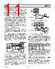
13 / 28 page  REV. B AD9753 –13– INTERLEAVED (2 ) MODE WITH PLL DISABLED The relationship between the internal and external clocks in this mode is shown in Figure 11. A clock at the output update data rate (2 × the input data rate) must be applied to the CLK inputs. Internal dividers then create the internal 1 × clock necessary for the input latches. Although the input latches are updated on the rising edge of the delayed internal 1 × clock, the setup-and-hold times given in the Digital Specifications table are with respect to the rising edge of the external 2 × clock. With the PLL disabled, a load-dependent delayed version of the 1 × clock is present at the PLLLOCK pin. This signal can be used to synchronize the external data. PORT 1 DATA X DATA Y tH tS tLPW tPD DATA X DATA Y PORT 2 IOUTA OR IOUTB DELAYED INTERNAL 1 CLK DATA IN tPD tD DATA ENTERS INPUT LATCHES ON THIS EDGE EXTERNAL 2 CLK EXTERNAL 1 CLK @ PLLLOCK Figure 11. Timing Requirements, Interleaved (2 ×) Mode with PLL Disabled Updates to the data at input Ports 1 and 2 should be synchro- nized to the specific rising edge of the external 2 × clock that corresponds to the rising edge of the 1 × internal clock, as shown in Figure 11. To ensure synchronization, a Logic 1 must be momentarily applied to the RESET pin. Doing this and return- ing RESET to Logic 0 brings the 1 × clock at PLLLOCK to a Logic 1. On the next rising edge of the 2 × clock, the 1× clock will go to Logic 0. On the second rising edge of the 2 × clock, the 1 × clock (PLLLOCK) will again go to Logic 1, as well as update the data in both of the input latches. The details of this are shown in Figure 12. RESET PLLLOCK EXTERNAL 2 CLOCK tRH = 1.2ns tRS = 0.2ns DATA ENTERS INPUT LATCHES ON THESE EDGES Figure 12. RESET Function Timing with PLL Disabled For proper synchronization, sufficient delay must be present between the time RESET goes low and the rising edge of the 2 × clock. RESET going low must occur either at least tRS ns before the rising edge of the 2 × clock, or t RH ns afterwards. In the first case, the immediately occurring CLK rising edge will cause PLLLOCK to go low. In the second case, the next CLK rising edge will toggle PLLLOCK. NONINTERLEAVED MODE WITH PLL DISABLED If the data at only one port is required, the AD9753 interface can operate as a simple double buffered latch with no interleaving. On the rising edge of the 1 × clock, input latch 1 or 2 is updated with the present input data (depending on the state of DIV0/ DIV1). On the next rising edge, the DAC latch is updated and a time tPD later, the DAC output reflects this change. Figure 13 represents the AD9753 timing in this mode. tH tS tLPW tPD DATA OUT PORT 1 OR PORT 2 1 CLOCK IOUTA OR IOUTB XX DATA IN PORT 1 OR PORT 2 Figure 13. Timing Requirements, Noninterleaved Mode with PLL Disabled DAC TRANSFER FUNCTION The AD9753 provides complementary current outputs, IOUTA and IOUTB. IOUTA will provide a near full-scale current output, IOUTFS, when all bits are high (i.e., DAC CODE = 4095), while IOUTB, the complementary output, provides no current. The current output appearing at IOUTA and IOUTB is a function of both the input code and IOUTFS and can be expressed as IOUTA = (DAC CODE/4096) × I OUTFS (1) IOUTB = (4095 – DAC CODE)/4096 × IOUTFS (2) where DAC CODE = 0 to 4095 (i.e., decimal representation). As mentioned previously, IOUTFS is a function of the reference current, IREF, which is nominally set by a reference voltage, VREFIO, and an external resistor RSET. It can be expressed as IOUTFS = 32 × IREF (3) where IREF = VREFIO/RSET (4) The two current outputs typically drive a resistive load directly or via a transformer. If dc coupling is required, IOUTA and IOUTB should be directly connected to matching resistive loads, RLOAD, that are tied to analog common, ACOM. Note that RLOAD may represent the equivalent load resistance seen by IOUTA or IOUTB as would be the case in a doubly terminated 50 Ω or 75 Ω cable. The single-ended voltage output appearing at the IOUTA and IOUTB nodes is simply VOUTA = IOUTA × RLOAD (5) VOUTB = IOUTB × R LOAD (6) Note that the full-scale values of VOUTA and VOUTB should not exceed the specified output compliance range to maintain specified distortion and linearity performance. VDIFF = (IOUTA – IOUTB) × R LOAD (7) |
|
Link URL |
| Lei ha avuto il aiuto da alldatasheet? [ DONATE ] |
Di alldatasheet | Richest di pubblicita | contatti | Privacy Policy | Collegamento alla scheda tecnica | scambio Link | Ricerca produttore All Rights Reserved©Alldatasheet.com |
| Russian : Alldatasheetru.com | Korean : Alldatasheet.co.kr | Spanish : Alldatasheet.es | French : Alldatasheet.fr | Italian : Alldatasheetit.com Portuguese : Alldatasheetpt.com | Polish : Alldatasheet.pl | Vietnamese : Alldatasheet.vn Indian : Alldatasheet.in | Mexican : Alldatasheet.com.mx | British : Alldatasheet.co.uk | New Zealand : Alldatasheet.co.nz |
|
Family Site : ic2ic.com |
icmetro.com |
 Italian ▼
 English
 Chinese
 German
 Japanese
 Russian
 Korean
 Spanish
 French
 Italian
 Portuguese
 Polish
 Vietnamese
 Indian
 Mexican
 British
 New Zealand