|
Motore di ricerca datesheet componenti elettronici |
|
|
Motore di ricerca datesheet componenti elettronici |
|
AD9753AST Scheda tecnica(PDF) 14 Page - Analog Devices |
|
|
|||||||||||||||||||||||||||||
AD9753AST Scheda tecnica(HTML) 14 Page - Analog Devices |
|
|
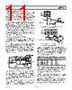
14 / 28 page  REV. B –14– AD9753 Substituting the values of IOUTA, IOUTB, and IREF, VDIFF can be expressed as VDIFF = {(2 DAC CODE – 4095)/4096} × (32 RLOAD/RSET) × V REFIO (8) These last two equations highlight some of the advantages of operating the AD9753 differentially. First, the differential opera- tion will help cancel common-mode error sources associated with IOUTA and IOUTB such as noise, distortion, and dc offsets. Second, the differential code-dependent current and subsequent voltage, VDIFF, is twice the value of the single-ended voltage output (i.e., VOUTA or VOUTB), thus providing twice the signal power to the load. Note that the gain drift temperature performance for a single- ended (VOUTA and VOUTB) or differential output (VDIFF) of the AD9753 can be enhanced by selecting temperature tracking resistors for RLOAD and RSET due to their ratiometric relation- ship, as shown in Equation 8. ANALOG OUTPUTS The AD9753 produces two complementary current outputs, IOUTA and IOUTB, that may be configured for single-ended or differential operation. IOUTA and IOUTB can be converted into complementary single-ended voltage outputs, VOUTA and VOUTB, via a load resistor, RLOAD, as described by Equations 5 through 8 in the DAC Transfer Function section. The differential voltage, VDIFF, existing between VOUTA and VOUTB, can also be con- verted to a single-ended voltage via a transformer or differential amplifier configuration. The ac performance of the AD9753 is optimum and specified using a differential transformer-coupled output in which the voltage swing at IOUTA and IOUTB is limited to ±0.5 V. If a single-ended unipolar output is desirable, IOUTA should be selected as the output, with IOUTB grounded. The distortion and noise performance of the AD9753 can be enhanced when it is configured for differential operation. The common-mode error sources of both IOUTA and IOUTB can be significantly reduced by the common-mode rejection of a trans- former or differential amplifier. These common-mode error sources include even-order distortion products and noise. The enhancement in distortion performance becomes more significant as the frequency content of the reconstructed waveform increases. This is due to the first order cancellation of various dynamic common-mode distortion mechanisms, digital feedthrough, and noise. Performing a differential-to-single-ended conversion via a trans- former also provides the ability to deliver twice the reconstructed signal power to the load (i.e., assuming no source termination). Since the output currents of IOUTA and IOUTB are complemen- tary, they become additive when processed differentially. A properly selected transformer will allow the AD9753 to provide the required power and voltage levels to different loads. Refer to the Applying the AD9753 Output Configurations section for examples of various output configurations. The output impedance of IOUTA and IOUTB is determined by the equivalent parallel combination of the PMOS switches associ- ated with the current sources and is typically 100 k Ω in parallel with 5 pF. It is also slightly dependent on the output voltage (i.e., VOUTA and VOUTB) due to the nature of a PMOS device. As a result, maintaining IOUTA and/or IOUTB at a virtual ground via an I–V op amp configuration will result in the optimum dc linearity. Note that the INL/DNL specifications for the AD9753 are measured with IOUTA and IOUTB maintained at virtual ground via an op amp. IOUTA and IOUTB also have a negative and positive voltage com- pliance range that must be adhered to in order to achieve optimum performance. The negative output compliance range of –1.0 V is set by the breakdown limits of the CMOS process. Operation beyond this maximum limit may result in a breakdown of the output stage and affect the reliability of the AD9753. The positive output compliance range is slightly dependent on the full-scale output current, IOUTFS. It degrades slightly from its nominal 1.25 V for an IOUTFS = 20 mA to 1.00 V for an IOUTFS = 2 mA. The optimum distortion performance for a single- ended or differential output is achieved when the maximum full-scale signal at IOUTA and IOUTB does not exceed 0.5 V. Applications requiring the AD9753’s output (i.e., VOUTA and/ or VOUTB) to extend its output compliance range should size RLOAD accordingly. Operation beyond this compliance range will adversely affect the AD9753’s linearity performance and subsequently degrade its distortion performance. DIGITAL INPUTS The AD9753’s digital inputs consist of two channels of 14 data input pins each and a pair of differential clock input pins. The 12-bit parallel data inputs follow standard straight binary coding where DB13 is the most significant bit (MSB) and DB0 is the least significant bit (LSB). IOUTA produces a full-scale output current when all data bits are at Logic 1. IOUTB produces a complementary output with the full-scale current split between the two outputs as a function of the input code. The digital interface is implemented using an edge-triggered master slave latch. With the PLL active or disabled, the DAC output is updated twice for every input latch rising edge, as shown in Figures 7 and 11. The AD9753 is designed to support an input data rate as high as 150 MSPS, giving a DAC output update rate of 300 MSPS. The setup-and-hold times can also be varied within the clock cycle as long as the specified mini- mum times are met. Best performance is typically achieved when the input data transitions on the falling edge of a 50% duty cycle clock. The digital inputs are CMOS compatible with logic thresholds, VTHRESHOLD, set to approximately half the digital positive supply (DVDD) or VTHRESHOLD = DVDD/2 ( ±20%) The internal digital circuitry of the AD9753 is capable of oper- ating over a digital supply range of 3.0 V to 3.6 V. As a result, the digital inputs can also accommodate TTL levels when DVDD is set to accommodate the maximum high level voltage of the TTL drivers VOH(max). A DVDD of 3.0 V to 3.6 V typically ensures proper compatibility with most TTL logic families. Figure 14 shows the equivalent digital input circuit for the data and clock inputs. |
|
Link URL |
| Lei ha avuto il aiuto da alldatasheet? [ DONATE ] |
Di alldatasheet | Richest di pubblicita | contatti | Privacy Policy | Collegamento alla scheda tecnica | scambio Link | Ricerca produttore All Rights Reserved©Alldatasheet.com |
| Russian : Alldatasheetru.com | Korean : Alldatasheet.co.kr | Spanish : Alldatasheet.es | French : Alldatasheet.fr | Italian : Alldatasheetit.com Portuguese : Alldatasheetpt.com | Polish : Alldatasheet.pl | Vietnamese : Alldatasheet.vn Indian : Alldatasheet.in | Mexican : Alldatasheet.com.mx | British : Alldatasheet.co.uk | New Zealand : Alldatasheet.co.nz |
|
Family Site : ic2ic.com |
icmetro.com |
 Italian ▼
 English
 Chinese
 German
 Japanese
 Russian
 Korean
 Spanish
 French
 Italian
 Portuguese
 Polish
 Vietnamese
 Indian
 Mexican
 British
 New Zealand