|
Motore di ricerca datesheet componenti elettronici |
|
|
Motore di ricerca datesheet componenti elettronici |
|
AS5047D Scheda tecnica(PDF) 25 Page - ams AG |
|
|
|||||||||||||||||||||||||||||
AS5047D Scheda tecnica(HTML) 25 Page - ams AG |
|
|
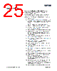
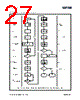
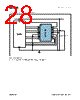
25 / 37 page  ams Datasheet: 2014-Jun-27 [v1-02] AS5047D – 25 Appl icatio n I n f o rm a t i o n Burn and Verification of the OTP Memory Step-by-step procedure to permanently program the non-volatile memory (OTP): The programming can either be performed in 5V operation using the internal LDO (1uF on regulator output pin), or in 3V Operation but using a supply voltage between 3.3V and 3.5V. 1. Power on cycle 2. Write the SETTINGS1 and SETTINGS2 registerswith the Custom settings for this application (Bit0 of Settings1 is a factory bit. For programming its mandatory to set this bit to 0). 3. Position the magnet at the desired zero position 4. Read out the measured angle from the ANGLE register 5. Write ANGLE [5:0] into the ZPOSL register and ANGLE [13:6] into the ZPOSM register 6. Read reg(0x0016) to reg(0x0019) → Read register step1 7. Comparison of written content (settings and angle) with content of read register step1 (Removing of Bit0 of Settings1 from the comparison is mandatory. Bit0 is preprogrammed) 8. If point 7 is correct, enable OTP read / write by setting PROGEN = 1 in the PROG register 9. Start the OTP burn procedure by setting PROGOTP = 1 in the PROG register 10. Read the PROG register until it reads 0x0000 (Programming procedure complete) 11. Clear the memory content writing 0x00 in the whole non-volatile memory 12. Enable OTP read / write by setting PROGEN = 1 in the PROG register 13. Set the PROGVER = 1 to set the Guard band for the guard band test(1). 14. Refresh the non-volatile memory content with the OTP content by setting OTPREF = 1 15. Read reg(0x0016) to reg(0x0019) → Read register step2 16. Comparison of written content (settings and angle) with content of read register step2. Mandatory: guard band test (Removing of Bit0 of Settings1 from the comparison is mandatory. Bit0 is preprogrammed) 17. New power on cycle, if point 16 is correct. If point 16 fails, the test with the guard band test1 was not successful and the device is incorrectly programmed. A reprogramming is not allowed! 18. Read reg(0x0016) to reg(0x0019) → Read register step3 Application Information |
|
Link URL |
| Lei ha avuto il aiuto da alldatasheet? [ DONATE ] |
Di alldatasheet | Richest di pubblicita | contatti | Privacy Policy | Collegamento alla scheda tecnica | scambio Link | Ricerca produttore All Rights Reserved©Alldatasheet.com |
| Russian : Alldatasheetru.com | Korean : Alldatasheet.co.kr | Spanish : Alldatasheet.es | French : Alldatasheet.fr | Italian : Alldatasheetit.com Portuguese : Alldatasheetpt.com | Polish : Alldatasheet.pl | Vietnamese : Alldatasheet.vn Indian : Alldatasheet.in | Mexican : Alldatasheet.com.mx | British : Alldatasheet.co.uk | New Zealand : Alldatasheet.co.nz |
|
Family Site : ic2ic.com |
icmetro.com |
 Italian ▼
 English
 Chinese
 German
 Japanese
 Russian
 Korean
 Spanish
 French
 Italian
 Portuguese
 Polish
 Vietnamese
 Indian
 Mexican
 British
 New Zealand