|
Motore di ricerca datesheet componenti elettronici |
|
|
Motore di ricerca datesheet componenti elettronici |
|
CC1010-RTY1 Scheda tecnica(PDF) 57 Page - Texas Instruments |
|
|
|
|||||||||||||||||||||||||||||
CC1010-RTY1 Scheda tecnica(HTML) 57 Page - Texas Instruments |
|
|
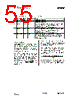
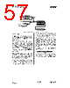
57 / 152 page  CC1010 SWRS047 Page 57 of 152 System Clk Divide by 12 Divide by 4 0 1 T0 / T1 T0M / T1M 0 1 C/T0 / C/T1 TR0 / TR1 GATE0 / GATE1 INT0 / INT1 TL0 / TL1 TH0 / TH1 TF0 / TF1 Timer 0 / Timer 1 interrupt request Clock Mux Reload Figure 9. Mode 2 operation for Timer / Counter 0 or 1 16.2.5 Mode 3 In Mode 3, which is illustrated in Figure 10, Timer 0 is operated as two separate 8-bit counters and Timer 1 stops counting and holds its value. TL0 is configured as an 8-bit counter controlled by the normal Timer 0 control bits. It counts either clock cycles divided by 4 or by 12 (as given by CKCON.T0M), or high to low transitions on T0 (as given by TMOD.C/ T 0). It is also possible to use the GATE function for TL0 to set INT0 as count enable. TH0 is locked into a timer function, and takes over the use of TR1 and TF1 from Timer 1. It counts clock cycles divided by 4 or 12 (as given by CKCON.T1M). TH0 may then generate Timer 1 interrupts. Timer 1 has limited usage when Timer 0 is in mode 3. This is because Timer 0 uses the Timer 1 control bit TR1 and the interrupt flag TF1. However, Timer 1 can still be used for baud rate generation and the Timer 1 count values are still available in the TL1 and TH1 registers. Control of Timer 1 when Timer 0 is in mode 3 is done through the Timer 1 mode bits. To turn Timer 1 on, set Timer 1 to mode 0, 1 or 2. To turn Timer 1 off, set it to mode 3. Timer 1 can count clock cycles divided by 4 or 12 or high to low transitions on the T1 pin. The GATE function is also available. In Mode 3, the timer timeout periods are determined by: ( )( ) xosc f TYx TxM CKCON T − ⋅ − = 256 . 8 12 where TYx is the contents of the THx or TLx register if this is reloaded in the interrupt handler, or 0 if no reload is done. |
|
Link URL |
| Lei ha avuto il aiuto da alldatasheet? [ DONATE ] |
Di alldatasheet | Richest di pubblicita | contatti | Privacy Policy | Collegamento alla scheda tecnica | scambio Link | Ricerca produttore All Rights Reserved©Alldatasheet.com |
| Russian : Alldatasheetru.com | Korean : Alldatasheet.co.kr | Spanish : Alldatasheet.es | French : Alldatasheet.fr | Italian : Alldatasheetit.com Portuguese : Alldatasheetpt.com | Polish : Alldatasheet.pl | Vietnamese : Alldatasheet.vn Indian : Alldatasheet.in | Mexican : Alldatasheet.com.mx | British : Alldatasheet.co.uk | New Zealand : Alldatasheet.co.nz |
|
Family Site : ic2ic.com |
icmetro.com |
 Italian ▼
 English
 Chinese
 German
 Japanese
 Russian
 Korean
 Spanish
 French
 Italian
 Portuguese
 Polish
 Vietnamese
 Indian
 Mexican
 British
 New Zealand